Milling is the most common, productive and popular method for obtaining flat straight surfaces, although the technological possibilities of the milling process are not limited to them.
Long flat surfaces are machined with end mills. In this case, it is desirable to fulfill the condition: the length of the machined surface is less than the diameter of the cutter.
For processing various kinds of ledges (usually not wide), cylindrical double-sided cutters are used. Grooves and open slots are obtained by using disc cutters. Semi-open slots are processed with disc and end mills. The closed groove is the most time-consuming in its execution and requires the use of special key cutters on semi-automatic machines using the pendulum feed method. The end mill is not used in this case, since it does not have the possibility of vertical plunge. One of the options for processing a closed groove with an end mill is to pre-drill a hole with a diameter equal to the width of the groove, and start processing from it.
Using a special set of cutters, T-slots are processed for fastening machine bolts: the first pass is the processing of a conventional vertical groove with an end or disk cutter, the second pass is carried out with a special cutter for T-slots, performing the lower wide step.
The processing of straight surfaces located at different angles relative to each other can be carried out with a set of standard cutters: say, a set of two disk cutters, disk and cylindrical, several angle cutters, and so on.
Shaped special cutters allow you to obtain surfaces of complex profiles: rounded groove, barrel groove, etc. Bayonet (screw) grooves on the shafts are also processed by end mills with strict alignment of the rotation of the workpiece with the movement of the tool (a special device or a universal dividing head is used). Large threads with large pitches and complex profiles can also be cut on milling equipment.
With any type of milling, two processing schemes are possible: up and down milling.
Up milling is characterized by a change in slice thickness from zero to a maximum. In this case, one of the components of the cutting forces tends to tear the workpiece off the table, which violates the overall rigidity technological system. But progressive infeed reduces load and wear. cutting tool.
Climb milling cuts the allowance in dynamics from maximum to zero. The vertical component of the cutting force presses the workpiece against the table, while the horizontal component acts on the screw-nut pair in the mechanism for moving the machine table. The feed may be jerky if the gap in the table gear is large enough. The tool works with a plunge impact, which negatively affects its condition. The roughness is increased compared to conventional milling.
The above is true for both cylindrical and disc cutters. The face mill uses both schemes, depending on the position of the tool relative to the surface before starting processing.
Rough milling allows you to get the 12th grade of accuracy and roughness Ra 6.3 micrometers, finishing - the 9th grade of accuracy and roughness Ra 3.2 micrometers, fine milling will provide accuracy up to the 6th grade and the surface finish parameter Ra 1.25 ..0.63 micrometers.
FLAT SURFACE MACHINING
LECTURE #18
The milling process is based on a combination of the main movement - the rotation of the cutter and forward movement- movement of the workpiece. When milling, use special equipment and technological equipment.
According to the classification of metal-cutting equipment, milling machines belong to the sixth group, which is divided into ten types. Zero type - reserve, the first includes vertical milling console machines, to the second type - copying and engraving, to the fifth - vertical milling consoleless, to the sixth - longitudinal, to the seventh - console wide universal, to the eighth - horizontal milling console, to the ninth - different.
Typically, milling involves relatively large cutting forces, which change sharply in magnitude, therefore, increased requirements are placed on the rigidity of the equipment.
On milling machines, you can process planes and bodies of revolution, threads, shaped curvilinear, helical surfaces, cut, cut blanks, trim ends, and perform various other operations of varying complexity.
There are concepts of cutting, cutting, cutting and trimming blanks. Rolled products are usually cut (with abrasive wheels, hacksaws) on milling and cutting machines, cutting is carried out with circular saws equipped with carbide plates.
Then, blanks of the required size for specific parts are cut from the parts, cut rolled on universal milling machines. Grooves, grooves, etc. are cut in these blanks.
For these operations, cutting and cutting cutters are used during milling. Ledges, grooves and lugs are processed with disk or annular cutters.
Cutting the ends of workpieces (shafts) is usually accompanied by their centering on milling and centering machines, which make it possible to machine the ends and centering with one setup.
Longitudinal milling and boring machines are designed for milling, boring, drilling, threading and other work. Milling machines allow, in particular, the sequential processing of holes, threaded profiles, end surfaces and grooves.
Distinguish between console and non-console machines.
For console machines, the table is located on a lifting bracket (console), while for non-cantilever machines, the table moves on a fixed frame.
Continuous equipment includes rotary and drum machines.
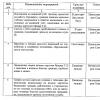
| a B C |
Rice. 18.1. Schemes for processing workpieces on longitudinal milling machines
Vertical milling, horizontal milling and longitudinal milling machines can be classified as universal equipment; spline-milling, carousel-milling, copy-milling - to specialized equipment.
CNC milling machines are usually equipped with a discrete system that sets the dimensions in coordinates within 0.01 mm and a tool magazine with 6-24 tools.
CNC machines are made with a vertical and horizontal spindle, console and consoleless - with simultaneous control in three coordinates.
On CNC milling machines, processing can be carried out both with a passing feed and with a counter feed. Automatic tool change and change in spindle speed, the availability of drilling, countersinking, reaming and boring along with milling, significantly expand the technological capabilities of such machines.
The basis of technological equipment is the tool.
A cutter is a blade tool with a rotational main cutting movement without changing the radius of the trajectory of this movement and with at least one feed movement, the direction of which coincides with the axis of rotation.
On a technological basis, milling cutters are divided for processing planes, slots, keys, gear, threaded, shaped surfaces, bodies of revolution, etc.
According to their design features, cutters differ in the arrangement of teeth (end, disk, angular, etc.), i.e., cutting teeth can be located on the cylindrical or end surface of the cutter; the direction of the teeth (straight, inclined, helical, etc.); teeth design (sharp-sharpened, backed); hull design (solid, prefabricated, etc.); fastening method (shell, end, etc.) and material of the cutting part of the cutter.
End mills with wide technological capabilities have become widespread. They can have a complex shape of the working profile, which allows them to process various surfaces.
(Fig. 18.2). The shape of the working surface of the end burrs is cylindrical (Fig. 18.2, a, b, c), cylindrical rounded (Fig. 18.2, d), spherical (Fig. 18.2, e), conical (Fig. 18.2, f, g, h) , torch-shaped rounded (Fig. 18.2, i), torch-shaped sharp (Fig. 18.2, j) and oval (Fig. 18.2, l, m).
These cutters are made both with and without chipbreakers. The taper angle of cutters is in most cases 14°, 25°, 30°, 45°, 60° or 90°.
End burrs are typically used on flat surfaces, fillets, non-straight welds, chamfers, complex profiles and curved profiles in hard to reach areas.
Rice. 18.2. Forms of the working profile of end mills
When removing large allowances, and, consequently, increasing the load on the tool, the use of burrs is impractical, in this case, use
use solid or prefabricated end mills. End mills can be made entirely of high speed steel or carbide, with brazed helical or rounded inserts. Such cutters can work with feed in the radial or axial and radial directions. End mills with mechanical fastening of non-regrinding inserts are widely used, for example, for chamfering. Firmly-
alloyed non-returnable inserts on end mills can have a different shape, for example, round or rounded, it is advisable to use such cutters for working on a copier.
The cutting elements of disc cutters are located on the outer cylindrical surface or end surfaces. They are designed for grooving, grooves and other recesses (Fig. 18.3).
Rice. 18.3. Diagrams of triangular disk cutters:
a - spur cutter; b - cutter with multidirectional teeth;
c - groove processing with a cutter with multidirectional teeth
They produce one-sided, two-sided and three-sided disk cutters, i.e., the cutting edges on them are located respectively only on the cylindrical (one-sided), on the cylindrical part and on one of the ends (two-sided), on the cylindrical part and both ends (three-sided). Carbide cutting elements are mechanically fixed in the cutter body.
Surface treatment by milling is carried out not only on special milling machines, but also on other types of equipment.
Face milling mainly provides multi-sided processing of the planes of body blanks. In end mills, the ratio of working diameter to its length is 4:6. Standard milling cutters have a diameter of 60 to 600 mm, which makes it possible to process large-width workpiece planes in one pass.
Face milling heads are made with adjacent cutting elements made of high-speed steel, hard alloy or mineral ceramics. Fastening of cutting elements is carried out in various ways. The simplest and most reliable fastening is provided when installing non-regrind plates. The fundamental difference between the methods of fastening can be considered the presence or absence of a system for regulating the position of the cutting elements on the tool body (Fig. 18.4, a). Unregulated systems of cutting elements are performed according to the modular principle (Fig. 18.4, b).
Modern machine-building production requires high productivity and good quality processing while reducing the number of operations. This can be achieved by using a combined tool (for example, a milling cutter - countersink).
At the same time, it is necessary to reduce the time for setting up a tool, which is achieved by processing workpieces with a set of cutters, and allows for a tolerance on a given processing width within ±0.025 mm.
The design of the mechanical fastening of the plates should provide high precision and durability of the body, rigid and backlash-free fastening of the inserts, creating conditions for unhindered chip flow, easy and fast change.
Rice. 18.4. Mounting schemes for non-regrindable inserts on a shell end mill:
a - diagram of the adjustable structure; b - modular design
When evaluating the milling process, it is necessary to take into account the direction of rotation of the cutter and feed, the distribution of cutting forces and processing modes. Face mills with helical carbide mechanically rigidly fixed tetrahedral non-sharpenable inserts provide milling of cast iron at a speed of 1 ... 2 m/s and a feed of 1 to 0.6 mm/tooth.
IN Lately whirl milling of shafts and threads is becoming more and more widely used. In whirl milling, the tool is installed in an annular holder, which is fixed in a special rotary device and rotates. The cutting edges of the tool are directed inside the holder. The feed can be carried out parallel to the axis of rotation of the vortex circuit, in the radial direction and along the circumference. Usually the feed is carried out in the radial direction.
The use of disc cutters equipped with carbide inserts has no fundamental differences in design from conventional tools (except that the cutting edges of the tool are directed inward). In the manufacture of crankshafts, instead of turning before grinding, it is possible to use whirl milling of main and connecting rod journals.
In round external milling, the milling cutter has the shape of a disc with a diameter of 600 ... 1100 mm, on which hard-alloy non-regrindable inserts are placed on the outer side. When processing the neck of the crankshaft, the cutter, rotating, is fed until the specified size is reached, then the shaft begins to rotate, during one revolution of which its neck is milled (Fig. 18.5). The main movement is made by the cutter.
With vortex (internal, enclosing) milling, the cutter also has the shape of a ring (disk), but the cutting carbide inserts are located inside the disk, the outer diameter of which is 800 ... 1000 mm. In this case, the teeth of the cutter are located on the inner surface of its body.
Please note that the profile of the cutter matches the negative shape of the crankshaft journal, therefore this tool can be used for a specific shaft size. With whirl milling, the shaft is not
Rice. 18.5. Scheme of external milling Fig. 18.6. Scheme of whirl milling
shaft: 1 - machined shaft neck; shaft: 1 - cutter; 2 - processed neck
2 - shaft cutter
rotates and the main (rotational) movement is performed by the tool (Fig. 18.6).
During processing, the cutter rotates eccentrically, making a planetary movement around a fixed shaft neck. Whirl milling according to
Compared with the external one, it has greater productivity, ensures smooth operation and tool life.
Milling with cylindrical cutters can be performed under conditions where their rotation and feed direction are the same (climb milling). In this case, the thickness of the cut layer gradually decreases from h max to zero (Fig. 18.7, a). If the cutter rotates against the feed direction (counter milling), then the cut thickness increases from zero to h max (Fig. 18.7, b).
When milling, cutting forces have a great influence on the accuracy of processing. When working with a spur cutter, the resultant cutting force R can be decomposed into circumferential (tangential) Р: and radial Р у components. The circumferential force affects the effective cutting power. The radial component pushes the cutter away from the workpiece.
Rice. 18.7. Cutting patterns for cylindrical milling:
a - climb milling; b - counter milling
The resultant force R can also be decomposed into two mutually perpendicular components - horizontal P h and vertical P v .
The horizontal component of the force affects the workpiece clamping mechanism and table feed. With counter milling, on the contrary, it seeks to squeeze (raise) the workpiece and the machine table (Fig. 18.7, b). During climb milling, the vertical component of the force presses the workpiece and the table against the guides of the machine (Fig. 18.7, a).
One of the features of milling is that the cutter tooth perceives an impact load, cuts off an uneven layer of chips, being in contact with the workpiece being machined for hundredths of a second. It is necessary to create cutting conditions such that several teeth are in operation at the same time, then the entry and exit of the teeth will not be accompanied by significant fluctuations in cutting forces, which will improve the quality of the machined surface and tool life. The helical arrangement of the teeth contributes to the uniform and smoother operation of the cutter.
Milling of flat surfaces.
A surface is considered geometrically flat if, by connecting any two points belonging to the surface, by a straight line, all points of this straight line will be on the surface. The quality of a flat surface can be easily checked by applying the edge of a curved ruler to it. The smaller the resulting gap, the higher the surface quality. The quality of plane processing is characterized by the following indicators:
Dimensional accuracy, ᴛ.ᴇ. compliance with the actual dimensions of the part indicated on the drawing;
Permissible deviations from the correct geometric shape of the resulting surface should not go beyond the tolerance for manufacturing inaccuracies (straightness tolerance, flatness tolerance).
The deviation of the location of individual faces of the part relative to other surfaces must be within the specified limits (deviation from parallelism, perpendicularity, inclination, symmetry, etc.)
When milling planes with face and cylindrical cutters, there are: rough roughing, roughing, semi-finishing, finishing. Rough roughing- processing with a large and uneven allowance - more than 8 mm, as well as work on the crust. Roughing– processing of planes with a relatively uniform allowance, without crust, with a depth of cut from 3 to 8 mm. Semi-finishing - processing of a plane with a uniform allowance and a depth of cut from 1.5 to 3 mm and a height of microroughness of the machined surface of not more than Rz = 40 microns. Finishing - processing of a plane with a uniform allowance and a depth of cut of up to 1.5 mm and a height of microroughness of the machined surface of not more than Ra = 20 microns.
Milling with cylindrical cutters. The teeth of a cylindrical cutter are located along a helix with a certain angle of inclination of the helical groove ω. The main dimensions of cylindrical cutters are cutter length L, cutter diameter D, hole diameter d, number of teeth z.
According to the direction of rotation, the cutters are divided into right-cutting and left-cutting. The choice of cutter type and size depends on the specific machining conditions. Cutters with a large tooth are used for roughing, with a small one for semi-finishing and finishing.
Choice optimal size cutters for given conditions can be made according to the following nomogram:
The procedure for using the nomogram is as follows: first, the cutter length is selected in accordance with the milling width. In this case, the length of the cutter must be greater than the width of the milling by 5%. Further, in accordance with the processing conditions, the diameter of the mounting hole is determined, then the diameter of the cutter, and finally the number of teeth. In this case, the following designations are used: T - hard-to-cut materials; C - materials of medium difficulty processing; L - easily processed materials. I - roughing; II - finishing.
Milling with face mills has a number of advantages over cylindrical milling. More rigid mounting on the arbor or spindle, smoother operation a large number simultaneously working teeth. For this reason, it is advisable to process planes with end mills.
The main dimensions of end mills are diameter, length, hole diameter, number of teeth. The standard stipulates that for face mills, each cutter diameter corresponds to a certain value for the length, hole diameter, and number of teeth. This circumstance should be taken into account when choosing the type of cutter.
The cutter diameter based on the milling width t is selected according to the following formula:
In this case, the minimum possible cutter diameter is selected from the ratio:
Smaller diameter cutters are less expensive, and therefore it is extremely important to give preference to them. Also, preference should be given to milling cutters equipped with carbide inserts, the smallest possible diameter for a given milling width, as this reduces the main machine processing time by increasing the minute feed. To improve the finish of the cut, it is essential to reduce the feed per tooth and increase the cutting speed.
Milling with a set of cutters is carried out by a group of cutters mounted on one mandrel. This method allows you to simultaneously process several surfaces. The use of a set of cutters is common in large-scale and mass production.
When milling flat surfaces with cylindrical and face mills, the following types of defects are possible:
Non-compliance with the dimensions of the part;
Form errors occur in the case of processing workpieces with a large and especially uneven allowance, as well as with insufficient rigidity of the technological system;
Errors in the location of machined planes. The reason is incorrect installation of the workpiece, poor cleaning of the supporting surface of the device from chips, the presence of burrs on the mounting surface of the part. When working with a set of cutters, the indicated defect may occur due to the incorrect location of the cutters on the mandrel;
Increased roughness can occur with improper sharpening of the cutter, high wear of the cutting edges, incorrect choice of cutting modes, insufficiently rigid AIDS system;
The undercutting effect occurs when the feed stops when the work stroke is not completed. In this case, the cutter continues to rotate and cuts into the workpiece under the action of the elastic forces of the mandrel, which was previously (before turning off the feed) under the action of cutting forces was bent. Another condition for the occurrence of the undercutting effect is the presence of a large gap in the screw-nut connection during climb milling. In this case, the cutting process proceeds in shocks. If processing is not stopped in a timely manner, then further work can lead, in addition to damage to the treated surface, to wear of the screw pair, breakage of the mandrel or cutter. In this case, it is extremely important to use the up milling method. In this case, it should be borne in mind that with up-and-down milling, the undercutting effect can occur if the feed per tooth is set too high.
Vibrations adversely affect the quality of the machined surface. Vibrations during milling occur due to the unevenness of the cutting process. To reduce vibrations, it is extremely important to strive to ensure that the number of simultaneously working teeth of the cutter is as large as possible, to comply with the conditions of down and up milling, as well as the condition of milling uniformity.
Milling of flat surfaces. - concept and types. Classification and features of the category "Milling of flat surfaces." 2017, 2018.
Milling technology for flat surfaces and bevels
Planes are usually milled with face and cylindrical cutters. The diameter of the end mill D (mm) is selected depending on the width B (mm) of milling, taking into account the ratio D=(1.3...1.8)B. When milling with face mills, preference should be given to an asymmetrical cutting pattern. Offset size (mm) k = (0.03...0.06)D (Figure -. 5.18).
The milling of planes is carried out in the following sequence: the workpiece is brought under the rotating cutter until it touches lightly, then it is removed from under the cutter, the machine spindle is turned off, the vertical feed dial (when milling a flat surface) or transverse feed (when milling a flat end surface) is set to the depth of milling , turn on the machine spindle and manually move the table with the workpiece until it touches the cutter, after which they turn on the longitudinal feed of the table. milling machine cutting
When processing with cylindrical cutters, the length of the cutter should overlap the required processing width by 10 ... 15 mm. The diameter of the cutter is selected depending on the width of the milling and the depth of cut t (mm).
With rough milling, dimensional accuracy is usually achieved, corresponding to the 11th and 12th qualifications, with finishing milling - to the 8th and 9th qualifications. In some cases, with fine milling, it is possible to obtain dimensional accuracy corresponding to the 6th and 7th grades. The roughness of the treated surface ranges from Rz 80 µm to Ra 0.63 µm. The lowest roughness parameters (Ra 1.25...0.63 µm) are obtained by fine milling. Another method for achieving low roughness parameters of flat surfaces on workpieces is the use of compound milling cutters, in the bodies of which roughing and finishing cutters are fixed. Finishing cutters are set lower than rough cutters by an amount equal to the depth of fine milling. One or more finishing cutters can be installed in the cutter body. With feed Sz = 1.5...2.5 mm/tooth and cutting speed v = 240...250 m/min, surface roughness Rz 5...2.5 µm is achieved.
When machining surfaces with end mills, due to the design of the tool holder, the cutting process is smoother than when milling with a cylindrical cutter.
End mills can mill vertical and small horizontal planes. The use of sets of cutters when milling planes allows you to increase the productivity of the machining process and process shaped surfaces. The set is a group of cutters installed and fixed on one mandrel.
A flat surface of a part located at a certain angle to the horizontal is called an inclined plane, and an inclined plane of small dimensions is called a bevel.
For milling inclined planes and bevels, the following tools are used:
o cylindrical, face and end mills with turning the workpiece to the required angle using a universal rotary plate (Fig. 5.19, a);

- o face and end mills with the cutter rotated to the required angle (Figure 5.19 - b)
- o special devices (Figure 5.19 -c, d) for processing with cylindrical and end mills;
- o angle cutters.
When milling with rotation to the required angle, the workpiece is fixed in a universal vice or on a universal plate and rotated through an angle so that the plane to be processed is parallel to the table surface.
Milling of inclined planes and bevels with face and end mills can be done by turning not the workpiece, but the tool spindle, by the required angle. This can be done on vertical milling machines, in which milling head with the spindle rotates in a vertical plane.
Milling workpieces with inclined planes and bevels in serial and mass production expedient to produce special devices, allowing you to install and fix workpieces without alignment.
Angle cutters process small inclined planes and bevels. In this case, there is no need to rotate the part and cutter.
Flatness error when machining with a face mill occurs if the axis of rotation of the cutter is not perpendicular to the surface to be machined or, otherwise, to the plane of the machine table. The plane turns out to be concave (Figure 5.20), and the larger, the larger the angle in and the smaller the diameter D of the end mill.

When milling a plane with a cylindrical cutter (set of cutters), the flatness error can be caused by the so-called undercutting, which is expressed by the appearance of a hole 1 on the machined surface (Figure 5.21) and is the result of a temporary cessation of the feed movement, as a result of which the cutter works for some time, rotating in one place. The elastic forces acting between the cutter and the workpiece tend to bring them closer together, which leads to the involuntary appearance of a hole (“workout”), and the greater the lower the rigidity of the LED system, the greater the cutting force and the longer the cutter stays in one place.

Flatness control the treated surface is produced with a curved ruler. Non-flatness during the processing of end surfaces is checked with a flat square or thickness gauge. Non-flatness, or deviation from flatness, is the greatest distance from the actual machined surface (plane) to the adjacent surface within the controlled area. An adjacent surface is a surface that is in contact with the real surface and located outside the material of the part so that the deviation from it of the most distant point of the machined real surface is minimal within the controlled area.
Inclined planes and bevels are controlled using templates and thickness gauges.
Installations for automatic welding of longitudinal seams of shells - in stock!
High performance, convenience, easy operation and reliable operation.
Welding screens and protective curtains - in stock!
Protection against radiation during welding and cutting. Big choice.
Delivery throughout Russia!
Planes are usually milled with face and cylindrical cutters. The diameter of the end mill D (mm) is selected depending on the width B (mm) of milling, taking into account the ratio D=(1.3...1.8)B. When milling with face mills, preference should be given to an asymmetrical cutting pattern. Offset size (mm) k = (0.03 ... 0.06) D (Fig. 5.18).
The milling of planes is carried out in the following sequence: the workpiece is brought under the rotating cutter until it touches lightly, then it is removed from under the cutter, the machine spindle is turned off, the vertical feed dial (when milling a flat surface) or transverse feed (when milling a flat end surface) is set to the depth of milling , turn on the machine spindle and manually move the table with the workpiece until it touches the cutter, after which they turn on the longitudinal feed of the table.
When processing with cylindrical cutters, the length of the cutter should overlap the required processing width by 10 ... 15 mm. The diameter of the cutter is selected depending on the width of the milling and the depth of cut t (mm).
With rough milling, dimensional accuracy is usually achieved, corresponding to the 11th and 12th qualifications, with finishing - to the 8th and 9th qualifications. In some cases, with fine milling, it is possible to obtain dimensional accuracy corresponding to the 6th and 7th grades. The roughness of the treated surface ranges from Rz 80 µm to Ra 0.63 µm. The lowest roughness parameters (Ra 1.25...0.63 µm) are obtained by fine milling. Another method for achieving low roughness parameters of flat surfaces on workpieces is the use of compound milling cutters, in the bodies of which roughing and finishing cutters are fixed. Finishing cutters are set lower than rough cutters by an amount equal to the depth of fine milling. One or more finishing cutters can be installed in the cutter body. With feed Sz = 1.5...2.5 mm/tooth and cutting speed v = 240...250 m/min, surface roughness Rz 5...2.5 µm is achieved.
When machining surfaces with end mills, due to the design of the tool holder, the cutting process is smoother than when milling with a cylindrical cutter.
End mills can mill vertical and small horizontal planes. The use of cutter sets for milling planes allows you to increase the productivity of the processing process and process shaped surfaces. The set is a group of cutters installed and fixed on one mandrel.
A flat surface of a part located at a certain angle to the horizontal is called an inclined plane, and a small inclined plane is called a bevel.
For milling inclined planes and bevels, the following tools are used:

When milling with rotation to the required angle, the workpiece is fixed in a universal vice or on a universal plate and rotated through an angle so that the plane to be processed is parallel to the table surface.
Milling of inclined planes and bevels with face and end mills can be done by turning not the workpiece, but the tool spindle, by the required angle. This can be done on vertical milling machines, in which the milling head with the spindle rotates in a vertical plane.
Milling workpieces with inclined planes and bevels in the conditions of serial and mass production, it is advisable to carry out in special devices that allow you to install and fix workpieces without alignment.
Angle cutters process small inclined planes and bevels. In this case, there is no need to rotate the part and cutter.
A flatness error when machining with a face mill occurs if the axis of rotation of the cutter is not perpendicular to the surface to be machined or, otherwise, to the plane of the machine table. The plane turns out to be concave (Fig. 5.20), and the larger, the larger the angle β and the smaller the diameter D of the end mill.

When milling a plane with a cylindrical cutter (set of cutters), the flatness error can be caused by the so-called undercutting, which is expressed by the appearance of a hole 1 on the machined surface (Fig. 5.21) and is the result of a temporary cessation of the feed movement, as a result of which the cutter works for some time, rotating in one place . The elastic forces acting between the cutter and the workpiece tend to bring them closer together, which leads to the involuntary appearance of a hole (“workout”), and the greater the lower the rigidity of the LED system, the greater the cutting force and the longer the cutter stays in one place.

Flatness control the treated surface is produced with a curved ruler. Non-flatness during the processing of end surfaces is checked with a flat square or thickness gauge. Non-flatness, or deviation from flatness, is the greatest distance from the actual machined surface (plane) to the adjacent surface within the controlled area. An adjacent surface is a surface that is in contact with the real surface and located outside the material of the part so that the deviation from it of the most distant point of the machined real surface is minimal within the controlled area.
Inclined planes and bevels are controlled using templates and thickness gauges.