Small business, which is based on the idea of printing on fabric: T-shirts, canvases, tablecloths, is gaining more and more popularity in the post-Soviet space. People love bright, exclusive things at a low price and willingly use the services of printing on textile materials. In order for the image to be of high quality, with high resolution, the question of choosing a special printer should be the main task of the entrepreneur: this is what will make you a name and generate income. If a fabric printer is purchased for home use, do not rush to spend your hard-earned money. There are several reasons for this.

Another thing is if the purpose of the acquisition textile printer –starting or expanding a business . In this case, downtime and drying out of the device are not threatened, just the volume and resource of the printer are important. With a print volume of about 200-300 products per day or small batches, but within 3-5 years without loss of quality, you need to think about purchasing professional equipment. A printer based on Epson 4880 with A2 print format belongs to the category of pros. The ability to draw small patterns in combination with the ability to fill large areas (40 by 80 cm) allows you to work with many materials: cotton, linen, leather, silk, knitwear. This model will cost the buyer 500-600 thousand rubles, while being the most reliable option in the line of Epson textile printers. The parts in the model are mostly metal, and the print resource is an impressive 20,000 prints. On Russian market there are several more worthy models of the pro class:

Epson F2000, several DTX-400 models from DecoPrint, a couple of models from Brother, Kornit, American I-Dot, and Texjet from Polyprint. When choosing a printer, you need to pay attention to the possibility and cost after-sales service A: The printer is a complex device, repairs and maintenance should be carried out at the service center by professionals. Be sure to ask the sellers how they work in case of a need for warranty repairs.
Refueling and repair
Brother and Epson F2000 printers do not allow the use of non-original consumables. The manufacturer guarantees the quality and reliability of the device only in case of use original cartridges, which the user must buy as soon as the old ones are over. But the price of the original Supplies for all printing devices, without exception, is prohibitively high, so be sure to check with the nearest before buying service centers the presence of ink and the possibility of refilling cartridges. When choosing a printer for textiles, pay attention to the number of colors - this will significantly save on refills or replacing cartridges in the future. For high-quality full-color printing, 4 colors (black, cyan, magenta, yellow) are enough, one cartridge per color, and four cartridges per white. At white color the highest expense. Choosing textile printer 8-9 colors, remember that print quality and brightness will not change much, and ink costs will double. The most common problem with ink printers has been and still is drying ink while idle when the printer is not being used.

To prevent clogging and drying of the nozzles, the printers are equipped with an ink recycling system and micro-cleaning during inactivity. Recirculation does not allow the ink to pass the full path from the cartridge to the spray nozzles and can only save you from thickening the ink, but not from drying out the print head. The function is useful, but the danger does not eliminate. Much more important is the presence of a micro-cleaning function in the device: in automatic mode and without your participation, the printer itself will skip the ink from the cartridges to the nozzles. Yes, a small amount of ink will go down the drain, but the user will protect his printer from a serious problem.
Sometimes the drying of pigment ink in the nozzles cannot be completely eliminated, and the only way out is to replace the print head, the cost of which is comparable to the price of a new printer. It is worth paying attention to the package of delivery of the printer: what is included in its package. An unpleasant surprise from many printer manufacturers may be the lack of ink in the basic kit when buying printer ink. Printing without ink will not work, so you will have to look for high-quality ink in specialized stores. It is not worth saving on ink - the quality of your products and the life of your device directly depend on the quality of consumables. As in cars: a sports car will not give full power on bad fuel, and the power unit will quickly become unusable.

Textile printer - choose wisely
Important nuances that you need to pay attention to when buying a textile printer:
- format and resolution;
- estimated circulation;
- brand (manufacturer);
- the number of flowers and the possibility of refueling in the future;
— the declared resource of printing of the device;
— compatibility with operating systems and programs that you use at work, the availability of drivers;
- Energy consumption;
- the weight of the device.

Do not make spontaneous purchases - carefully study the offers, read the forums, seek advice from service engineers: they will give comprehensive information about the weaknesses of a particular model. The comfort of your work with a textile printer, maintenance costs and its service life depend on this.
The simplest, most affordable and most effective method of making printed circuit boards at home is the so-called "laser-iron" (or LUT). The description of this method can be easily found by the corresponding keywords, so we will not dwell on it in detail, we will only note that in the simplest version, all that is needed is access to laser printer and the most ordinary iron (not counting the usual materials for etching circuit boards). So, the alternatives this method No?
Developing a variety electronic devices, used, for example, when testing monitors, we used several ways to mount electronic components. At the same time, printed circuit boards as such were not always used, since when creating prototypes and devices in a single copy (and often it turned out to be both), subject to inevitable errors and modifications, it is often more profitable and more convenient to use factory-made prototyping boards, performing wiring with a thin stranded wire in Teflon insulation. Even the most famous companies do this in a similar way, which is demonstrated by the prototype of the AIBO toy robot from Sony.
The stores sell relatively cheap double-sided tinned and even with plated holes and a protective mask on the jumpers, breadboards of very high quality.

Note that such prototyping boards make it possible to achieve a high mounting density without much effort, since there is no need to take care of the wiring of the conductive tracks. However, for example, when developing power blocks and when using elements with non-standard pin spacing or their geometry, as well as when using surface-mounted elements (which we do not do yet), it becomes difficult to use ready-made prototyping boards.
As an alternative to prototyping boards, we used the methods of cutting the foil in the gaps between the conductive pads and the mentioned LUT method. The first method is applicable only in the case of the simplest wiring options, but it does not require anything at all, except for a sharp knife and a ruler. The LUT method gave generally good results, but some variety was desired. We considered the using method too laborious and requiring the use of caustic chemicals, which is not always acceptable at home. The case allowed us to learn about another way - about the method of direct inkjet printing template on foil fiberglass ( keywords to search for English language- Direct to PCB Inkjet Printing).
The method is divided into the following steps:
- Proper seal pigmented
- Thermal fixing of the printed template. In this case, the ink becomes resistant to the etching solution.
- Removing ink from the printed circuit board.
There is also an alternative:
- Printing in general any printed circuit board template ink directly on foil fiberglass using, as a rule, a modified inkjet printer.
- Powdered toner from a laser printer/copier is sprayed onto the still wet ink, and the excess toner is removed.
- Thermal fixing of the printed template. This fuses the toner and securely adheres to the foil.
- Etching of unpatterned sections of the foil in the usual way, for example, using ferric chloride III.
- Removing caked toner from the printed circuit board.
We did not consider the second option because of the reluctance to work with powder toner, which can stain everything around with an accidental wrong movement or sneeze. All of the implemented direct inkjet template printing methods that we found used Epson inkjet printers. Also, the type of ink, or rather the type of dye used in them - pigment, we are steadily associated with printers of this manufacturer, so we started the search for a suitable printer from the Epson catalog. Apparently, Epson has, or at least had, models that can print on media up to 2.4 mm thick (and not only CD / DVDs), for example, the Epson Stylus Photo R800, but this the model is no longer produced, but we did not know in advance whether it would be possible to use something from modern analogues (obviously not cheap). As a result, it was decided to look for the cheapest model that uses pigment ink. The model was found - Epson Stylus S22. This printer turned out to be the cheapest among all Epson printers - the price for it was less than 1500 rubles, then, however, it grew noticeably: in Moscow retail (the ruble equivalent is in the tooltip) - N / A (0) .

A cursory examination showed the need for significant changes in the design of the printer, as it provided for printing on flexible media with its bending when moving from the top input tray to the output tray. The sequential modification described below was synthesized from several iterations, since after the next assembly it turned out that certain changes needed to be made to the design. Therefore, the possibility of small inaccuracies in the description of this process cannot be ruled out. The modification has two main goals. Firstly, to ensure a straight line without bends and height differences, the media supply, for which you need to change, but actually re-create the input and output trays. Secondly, to provide the ability to print on thick materials - up to 2 mm, for which it is necessary to raise the assembly with the print head and its guide slide. So:
1. Unscrew the two screws on the rear wall and remove the casing, releasing the latches with which it still clings to the bottom.

2. Disconnect the control panel cable from the main board, unscrew the two self-tapping screws securing the control panel,

release the cable from the control panel and set it aside. It is still useful, unlike the casing of the case.
3. Unscrew the 4 screws of the paper feed unit, release the wires going to the carriage motor, press the feed roller gear lock, remove the feed roller stand and the entire feed unit, remove the paper side clamp - these parts will no longer be useful.


4. Unscrew the self-tapping screw on the absorbent pad tray and on the power supply, disconnect the drain hose from the tray and the cable from the PSU on the main board, remove the absorbent pad tray and the PSU. Put them aside - still useful.


5. Unscrew the two self-tapping screws of the strip with the rollers pressing the outgoing sheet, remove this assembly and move it to a pile with “extra” parts.

6. On the right, unscrew the self-tapping screw and the screw securing the sled along which the print head moves.

Remove the spring that presses the sled.

Remove the carriage ruler spring (tapes with strokes) and the ruler itself.

Unscrew the two screws securing the main board,

and press it away from the slide (be careful with the paper sensor!). Unscrew the screw securing the sled, located under the main board.

On the left, unscrew the self-tapping screw securing the sled.

Disconnect the feed motor connector (J7) from the main board.

Disconnect the spring on the left side of the sled.

Remove the slide assembly with the print carriage and main board.

7. On the left, unscrew the self-tapping screw of the broach shaft lock,

remove the shaft and its retainer.

8. Remove all additional guides at the beginning of the broach, which are attached to the latches.

9. Using a blade from a hacksaw for metal and needle files, cut a window in the bottom from the side racks, to the bottom of the feed tray and to the feed shaft. It is convenient to use the existing grooves and holes in the bottom. Cut off the burrs with a knife, remove the sawdust.

10. Now you need to create a direct feed tray. To do this, you can use two pieces of aluminum corner 10 by 10 mm 250 mm long and part of the original paper support in the input tray (you can use any rigid plate of a suitable size). The corners are attached with M3 countersunk screws as shown in the photos below. On the vertical planes of the printer case, to which the corners are attached, grooves should be cut out so that the input tray can be moved slightly up and down to fine-tune its position.


On the right corner, you need to cut off the vertical corner, otherwise the right pressure roller will rest against it. Also on the pallet you need to cut a groove opposite the paper sensor (although, apparently, you can not do this).

And put a piece of the tube on the antenna of the paper sensor, thereby lengthening it a little.

11. Disconnect the feed shaft position sensor (one screw), cut off the stopper on the sensor housing, and fix it by sliding it as far down as possible.

During subsequent assembly, check that the disk with strokes is placed in the middle of the sensor slot and does not touch its edges.
12. Under the three attachment points of the sled, place a two washers with a hole of 4 mm each 1 mm thick. When using wide washers in two places, they need to be filed so that they do not rest against the body elements.


13. Remove the pressure rollers, put on them 2-3 layers (at least 3 layers on the central pair of rollers) of a heat-shrinkable tube with shrinkage of the intermediate layers with a hot air gun or other heating method. With a file, deepen the grooves for the rollers so that they rotate freely. Insert rollers into holders.

14. In the parked position, as well as in the process of cleaning the nozzles and initializing new cartridges, a pad with a rubber gasket is pressed against the bottom surface of the print head, where the nozzles are located. From below, a tube is connected to the pad, going to the vacuum pump. When cleaning, the pump sucks ink from the cartridges, and during storage, the nozzles are protected from drying ink in them. Therefore, it is important to ensure that the rubber seal fits snugly against the head, but due to the upward movement of the sled and print head, this condition may not be met. It is necessary to increase the travel of the pillow in the crib. To do this, you will have to remove or at least move the pump away - unscrew the two screws and squeeze out the two latches.


Then remove the spring that tightens the pillow bed, remove the bed-pillow assembly, and disconnect the tube extending from the pillow. Next, cut with a knife about 1.5 mm in the right places sections of the body of the pillow and the crib, increasing the vertical stroke of the pillow. Then assemble the knot back. Since automatic cleaning of nozzles and initialization of cartridges led to strange results when using non-original cartridges, we decided to disconnect the pump from the pad, for which we used a piece of tubing and a tee. To remove excess ink or when manually washing the pad, you can connect a syringe to the tee, or simply pinch its outlet with your finger and, by scrolling the feed shaft back (by the gear in front on the left), use the printer pump.
15. Reassemble the printer in reverse order. When installing the feed shaft, carefully clean the seats of chips and dust and apply a layer of grease to them and to the corresponding areas of the shaft. After installing the roller, you need to adjust the feed tray. By loosening the screws securing the tray to the side walls of the case, using a rigid plate of a suitable size (for example, a piece of fiberglass), you need to ensure that the movement of the plate from the feed tray along the feed shaft and along the shaft in the output tray is even, without differences in height. You should also ensure that the guides of the feed tray are strictly parallel and perpendicular to the feed shaft. Having found such a position of the feed tray, the screws should be tightened and it is advisable to fix it on the side of the nuts with a drop of varnish. Then continue building. On the right side, due to the shift of the sled upwards, or rather, the mounting hole will not coincide with the hole in the case rack - you can file the hole and fix the sled with a screw, or you can leave it as it is.

The tray of the absorbent pad, having previously shortened its right post, we installed in its original place, fixing it at two points with hot glue. The power supply did not fit in its original position, so we did not find anything better than simply fixing it with a plastic tie on the left stand of the printer frame. We screwed the control panel to the eyelet on the PSU.


The original output tray causes the output to kink, so it needs to be upgraded to ensure a smooth horizontal output. To do this, just put something a little less than 3 cm high under the tray, and put a couple of thick magazines or a stack of paper on the tray. However, after a while, we replaced this design with a tray made from the casing of a non-working DVD player. What needs to be done with the casing in order to turn it into a tray is clear from the photographs, however, here everyone can use their imagination and improvised material.


Result:


Shift the sled up to b O a larger value than described above is associated with some difficulties. Problem areas are at least the feed shaft position sensor, the right bracket of the carriage ruler, and the parking assembly. Perhaps something else. As a result, the thickness of the material on which the modified printer can print is about 2 mm or a little more, therefore, with a textolite 1.5 mm thick, the substrate should not be thicker than 0.5 mm, while it should be rigid enough to move blanks for printed circuit boards. A suitable and affordable material turned out to be thick cardboard, for example, from a folder for papers. The liner must be cut exactly to the width of the input tray, as any horizontal misalignment will affect print accuracy. In our case, the substrate turned out to be 216.5 by 295 mm in size. The original feed unit cannot be used, so the liner must be manually fed under the pressure rollers, but the paper sensor must not be activated. Because of this, it will be necessary to make a cutout in the substrate for the antenna of the paper sensor, in our case at a distance of 65 mm from the right edge, 40 mm deep and 10 mm wide. In this case, printing starts at a distance of 6 mm from the bottom of the cutout, that is, 6 mm before the edge of the media that the printer detects. Why this is so, we do not know. To fix the blanks on the substrate, it is convenient to use double-sided adhesive tape. The pinch rollers press the liner against the feed roller with great force, so the rollers must not run in or out of the workpiece to ensure a smooth print feed. To ensure this condition, before, after and possibly from the sides of the workpiece, you need to glue the material with the same thickness. This will also make it easier to position the workpiece for serial and/or duplex printing.
The original cartridges ran out fairly quickly, but overall the results with the original inks were very good. good. However, it was decided to purchase refillable cartridges and compatible inks.


The soul did not rest on this, attempts were made to modify the ink in order to increase the content of the polymer component in them. As a result of these experiments, the nozzles with black ink were clogged by 90%, with magenta - by 50%, one nozzle did not work in the "yellow" row, and only the cyan ink nozzles remained fully operational. However, one color is enough for printing templates. Since magenta ink showed the best result, it was they who were refilled in the cyan ink cartridge.
1. Prepare the workpiece surface. If it is relatively clean, then it is enough to degrease it with acetone. Otherwise, degrease, clean with an abrasive sponge, and, to form an oxide layer, place in an oven for 15-20 minutes at a temperature of 180°C. Then cool and degrease with acetone.
2. Using double-sided adhesive tape and auxiliary textolite scraps, fix the workpiece on the substrate.
3. Convert the template to the pure color that will be used when printing. In our case, in blue (RGB = 0, 255, 255). Conduct test print(it is possible not to use the whole template, but only the overall points, for example, corners), if necessary, in the program used for printing, correct the position of the template, wash off the previous result with acetone, repeat, if necessary, the correction procedure.

4. Print the template on the blank. The best results are obtained with the following settings:


5. Dry the workpiece in air for 5 minutes, you can use a hair dryer to speed it up. Then detach the workpiece from the substrate and carry out preliminary fixing in the oven for 15 min (time from turning on the oven) at 200°C at peak. Cool the workpiece.
6. For precise positioning of the second layer, you can drill several small diameter holes, for example, 1 mm in diameter, at the mounting points of the future board. Fix the workpiece with the surface for the second layer up, while the double-sided adhesive tape must be glued to the completely painted areas of the first layer. If the workpiece is tightly clamped between the two plates front and back, then double-sided adhesive tape is not necessary. Degrease the workpiece with acetone.
7. Position and print - repeat steps 3 and 4.

8. Dry the workpiece in air for 5 minutes, you can use a hair dryer to speed it up. Then detach the workpiece from the substrate, fix it on stands, for example, made of paper clips, place it in an oven, and fix it for 15 minutes (time from turning on the oven) at 210°C at peak. Cool the workpiece.


9. Inspect the workpiece, places with suspicious thin layer ink (for example, next to holes or adhering dust particles) to paint over with a waterproof marker. Etch the workpiece. In order for the surface of the workpiece to keep a distance from the bottom of the container, you can insert toothpicks into the holes (1 mm in diameter used to position the second layer), so that the sharp tip comes out 1.5-2 mm, and the thick one is bitten off to the same height. When etching, periodically turn the board over and check readiness.


Wash off the ink with acetone.


Important notes.
1. In order for the ink used to become resistant to the etching solution, it must be kept for about 15 minutes (time from turning on the oven) at a temperature of about 210 ° C at the peak (obtained using a thermocouple located next to the workpiece). The interval is narrow, since when it is exceeded by 5-10 ° C, the textolite begins to collapse, when it is lowered, the ink is washed off with an etching solution. The exact conditions in a particular case must be selected empirically. For control, you can use the test with a cotton swab. If a cotton swab moistened with water easily washes off the ink, then you need to increase the temperature, if it does not wash off, or only slightly stains, then resistance to the etching solution has been acquired. Even if a cotton swab moistened with acetone is difficult to wash off the ink, then the resistance to the etching solution is very good. This way you can select the ink and fusing conditions that give you the best results. It should be noted that we used an electric grill oven, turned on only the upper heating element, and when the ink was finally fixed, the oven thermostat was set to 220°C.
2. Printing reproducibility reaches about 0.1 mm, so if necessary, you can print it a second time over the first side of the template, with intermediate drying directly on the substrate with a hot air gun (with adjustable temperature) or a household hair dryer set to the maximum temperature. Drying is needed so that the pressure rollers do not lubricate the previous layer.
3. The production of two sides can be done sequentially. First, print and fix the first side, and protect the foil on the second, for example, acrylic paint from a balloon. Etch the first side, remove the protection from the second side with acetone, print and fix the second side, protect the first with ink, etch the second side, and remove the protection from the first.
4. You need to print as follows: first send the print job, wait until the printer reports that there is no paper, then carefully slide the substrate with the fixed workpiece under the pressure rollers, scrolling the feed roller by the gear in front on the left, and then press the button to continue printing. If there are short breaks between print sessions, the printer will not perform a short cleaning procedure, so you can load the substrate with the blank first, and then send the print job.
5. Special cleanliness must be observed, as any dust that has fallen on wet ink on the workpiece can lead to a defect.
Several double-sided printed circuit boards were made in this way, and although the tracks at than 0.5 mm were not used, the possibility of obtaining tracks with a width of 0.25 mm was demonstrated in the test areas, and this is clearly not the limit of this method.

P.S. An example of a double-sided board with 0.25 mm tracks (during the design, the norms of 0.25 mm for the width of the tracks and for gaps were laid down, but with manual fine-tuning, the distances between the tracks were increased as much as possible). Note that in the manufacture of double-sided boards, apparently, it is still more reliable to print and etch the sides sequentially. Side 1:

Side 2:

Three types of defects can be seen:
1. Linear distortion, which is apparently caused by the fact that one side was printed in a fast two-pass mode, and the other in a slow single-pass mode. That is, it is better to print both sides in the same mode.
2. In places, the tracks are slightly widened due to ink spreading. This defect can be avoided by carefully preparing the surface - degrease with a piece of cloth soaked in acetone, then wipe thoroughly with a dry cotton swab.
3. From one edge of the track and the pads were etched noticeably more. This happened due to overheating, as a result of which the ink became very dark and began to peel off. This means that it is necessary to carefully monitor the uniformity of heating (choose a place in the oven where the heating is more uniform) and in no case allow overheating - the ink should noticeably darken, but not acquire a dark gray tint.
However, these defects did not turn out to be critical, and as a result, without any wiring correction, we got a fully functioning device.

Fabric printing at home
Using a conventional inkjet printer, which most readers have at home, you can put inscriptions and drawings on clothes, as well as make flags, pennants and other small-sized unique items.
Image transfer media
Virtually any inkjet printer or MFP, both modern and long-discontinued, can print images on special media for transfer to cotton and blended fabrics that can withstand prolonged heat. The structure of such media includes a dense paper base and a thin elastic layer that is attached to the fabric when heated - it is on its surface that ink is applied during the printing process.
Each of the world's leading manufacturers of inkjet printers has branded print media for transferring images to fabric. For example, Canon has T-Shirt Transfer media (TR-301) in its product line, Epson has Iron-On Cool Peel Transfer Paper (C13S041154), and HP has Iron-On T-Shirt Transfers (C6050A). The retail packages of the listed media (Figure 1) contain 10 sheets of A4 paper.
![]()
In addition, third-party manufacturers also produce media for transferring images to fabric. For example, Lomond, a well-known company in our country, offers several options at once: Ink Jet Transfer Paper for Bright Cloth (for light fabrics), Ink Jet Transfer Paper for Dark Cloth (for dark fabrics) and Ink Jet Luminous Transfer Paper (suitable for dark and light fabrics, and thanks to fluorescent additives, the image glows in the dark). The Lomond media listed (Figure 2) is available in packs of 10 and 50 sheets in A4 and A3 sizes.
Image preparation
Image preparation and output can be performed in any raster or vector graphics editor. However, it should be borne in mind that due to the peculiarities of both inkjet technology and the thermal transfer process itself, an image transferred to fabric using a special medium will differ markedly from the same image printed by the same printer on ordinary, and even more so on photographic paper. In particular, the image transferred to the fabric is characterized by lower contrast, smaller color gamut and poorer reproduction. light shades compared to a control print made even on regular office paper. In order to minimize losses when preparing raster images (photographs, reproductions, etc.), it is necessary to increase their contrast and saturation. When creating and editing vector images, it makes sense to use pure, saturated colors to fill objects and outlines, and avoid using light shades and very thin lines whenever possible.
Photos, as well as vector and raster drawings with a lot of halftones and gradient transitions, will look best on products made of white fabric with a fine texture. The fact is that the color of the fabric, other than white, can noticeably distort the colors of the original image. For this reason, to transfer an image to a melange or colored fabric, it is advisable to create monochrome designs or images with a limited number of colors.
For the most efficient use of special media, several separate small-sized images can be arranged on one sheet like pattern details, leaving 10-15 mm wide gaps between their borders.
Seal
So, the image is ready. In the printer settings, select the thermal transfer media, the size and orientation of the sheets to be used (Figure 3). In order for the inscriptions transferred to the fabric to be read normally, and the images to “look” in the same direction as the original, they must be printed in a mirror image. To do this, activate the option to mirror the printed image in the printer driver settings (in Russian versions it can be called "mirror" or "flip horizontally", in English - flip or mirror). If the driver of the printer you are using does not provide such an option, look for it in the print settings of the program from which you plan to print the picture (Fig. 4 and 5). To check the correctness of the selected settings, use the preview mode.


Transfer image to fabric
To transfer the printed image to the fabric, an ironing press is best suited - it will provide the most durable fixation of the pattern. However, if among your household utensils there is no such device, you can use a regular iron.
Prepare a desktop with a flat and hard surface that is resistant to prolonged heat (an ironing board will not work for this purpose, unfortunately). In addition, you will need a piece of clean matter.
Cut out the image printed on a sheet of special media, stepping back 5-6 mm from its borders.
Set the iron control to the correct position. maximum power. If your model is equipped with a steamer, turn it off. Leave the iron turned on for a while so that it warms up to the maximum temperature.
Since the power and temperature conditions of different models of irons differ, it will be necessary to select the optimal transfer time experimentally. To do this, it makes sense to print a few test images of a small size and try to transfer them to an unnecessary piece of fabric.
After making sure that the iron is warm, put a piece of clean cloth prepared in advance on the work table and smooth it thoroughly so that there are no wrinkles or folds. Then lay on top of this fabric the product on which you plan to transfer the pattern. Prepare the surface for transferring the image by ironing it.
Position the cutout print face down where you want it to be. For the best fixing of the image, it is desirable to use the widest part of the working surface of the iron. When translating a large image, it is best to smooth the sheet in several passes, slowly moving the iron tightly pressed against the table along the long side of the drawing (Fig. 6). The duration of one pass should be about 30 s.
Turn the iron 180° and repeat the above procedure, starting at the opposite end. Then carefully iron the edges of the image to be translated by moving a tightly pressed iron around the perimeter of the image.
![]()
using an iron
After completing the above steps, allow the product to cool for one to two minutes, and then carefully separate the paper base by taking it at any of the corners. Please note that it will be much more difficult to remove the base from a completely cooled product.
If you plan to apply several images or inscriptions on the same product, you must place them in such a way that they do not overlap each other.
Finished Goods Care
Products with images applied by the described method are best washed in cold water using a powder for colored things. T-shirts and shirts with translated images must be turned inside out before being loaded into the washing machine. Be prepared for the fact that after the first wash, the colors in the image will become less bright and saturated - this is quite normal.
Well-fixed images can withstand several dozen washes with minimal loss of brightness and saturation. However, optimal preservation is ensured by hand washing.
The list of printing equipment includes professional and universal equipment. A fabric printer belongs to the second group. Images on white and colored textiles are bright and durable. Different materials have their own technology and suitable equipment.
Devices for direct printing
The digital method is one of the most accessible and efficient. No need for intermediate forms, you can work with any kind of fabric. The technique is based on the impregnation of the textile base with water-soluble paint, followed by heating. Under influence high temperatures the pattern is firmly fixed on the surface.
IN technological process 2 main devices are involved: a printer and a heat press. First, a drawing layout is developed on a computer - in a graphic editor.
The item is then placed into a direct print printer. The image is transferred from digital source for textiles. The paint quickly penetrates the fabric and lays down evenly. The picture is bright, with precise contours, visible from both sides and does not fade for a long time.
Famous brands: HP, Brother, Epson, JETEX, DreamJet, Power Jet. The most demanded machines are direct printing, creating drawings in A4 and A3 sizes.
The price of equipment working on mixed materials of light colors starts from 100 thousand rubles. Printers for printing on natural cotton fabrics cost 400-650 thousand rubles. Models working with both white and colored textiles cost the same amount.
 Large print shops use industrial textile printers
Optional equipment
To fix the pattern, a flat heat press is used (another name is tablet). Textiles (for example, a T-shirt) are laid on the work surface and pressed with a stove that heats up to 220-250 degrees. The high pressure and temperature fuse the dye into the fabric.
According to the opening mechanism, tablet presses are vertically folding and rotary. In the first case, the plate rises up. In the second, it moves to the side relative to the table.
Heat presses also vary in size. heating plate. The most popular formats are 380 x 380 and 400 x 500 mm. They can be used to draw images on different types flat surfaces: clothes, scarves, towels, bed linen.
When buying, pay attention to the power of the press, ways to adjust pressure and temperature, types of processed materials. Check the smoothness of the plate and the uniformity of its heating.
A simple manual unit costs 15-35 thousand rubles. Automatic control raises the price to 100 thousand rubles.
 Popular heat press brands: HIX, Insta HTP, AcosGraf, Sefa, ZnakPress, Transfer Kit.
sublimation equipment
Thermal transfer technology is based on transferring an image to a textile base through an intermediate carrier. If you apply a pattern to a synthetic fabric, you get a textured, durable print. On cotton, the images are quickly washed off when washed.
For thermal transfer you need:
- a computer with a package of graphic programs for creating layouts;
- sublimation printer;
- thermopress flat.
A sublimation printer can be replaced with a regular digital one. When buying, you just need to clarify whether it is refilled with sublimation ink.
The drawing is printed on sublimation paper. It does not absorb paint, does not allow it to spread and forms a clear image with a smooth surface.
The product is sent to a heat press. Under the influence of high temperatures and vacuum, the paper burns out, and the sublimation ink is firmly soldered to the fabric. The same types of thermal presses are used in the work as for digital direct printing.
 Textured pattern looks great on t-shirts and other clothing
Screen printing machines
This impression technique is based on creating a pattern using special stencils, each of which corresponds to a specific color. First, the digital image is divided into parts by shades. Then, on separate sheets of paper, the silhouette of the drawing is printed in one color and covered with photographic emulsion.
After that, the stencil machine is connected to the work. On it, several actions are sequentially performed:
- transfer the pattern to a frame with a stretched mesh;
- pull textiles onto the machine;
- a stencil with ink is installed on top and they are forced through small cells.
Single-colour presses have one printing section. Two-color and multi-color models are carousel-type devices. On them, you can simultaneously cover several things with a pattern without changing the stencils. Each paint is in a separate section and is pressed through its grid.
 The paint can be applied to the working field with a brush or roller
According to the level of mechanization, stencil machines are divided into 3 types:
- With manual control. Simple device, convenient operation, can be used at home. Not suitable for large runs. The minimum price is 35 thousand rubles.
- Semi-automatic. They cost from 70 thousand rubles. Increased productivity - the process of printing and removal of products is automated. The lining is done by hand. In intermediate steps, the textile printer ensures that the ink is dried on the garment.
- Automatic. Professional stencil equipment with high performance. All processes are automated and do not require manual labor. The minimum cost of equipment is 150 thousand rubles.
Well-known manufacturers of stencil equipment: Fusion, Chameleon, Economax, Kruzer, Sidewinder.
Allow the ink to dry after each color has been applied and when printing is complete. In addition to manual and semi-automatic fabric printers, you need to purchase drying device chamber or tunnel type. Conveyor dryers are expensive (from 250 thousand rubles) and are suitable for large industrial production.
Auxiliary technology for screen technology:
- machine for making stencils;
- exposure device;
- washing cabin for processing mesh frames.
In general, the kit will cost 150-200 thousand rubles.
Thermal application on fabric
Thermal application technology is the simplest of all types of textile printing. The pattern for clothes is created manually from individual elements of the adhesive film. Then the fabric is placed in a heated press, which fixes the application. Use the same heat presses as for direct printing. At home, you can fix the picture with an iron.
The film is printed on a conventional digital or inkjet printer. Vinyl, velvet, suede are also used as consumables.
Overview of flagship models of textile printers
Sublimation fabric printer with a compact size, 64" (1626mm) print width. Recommended for large print runs. Works with high density inks that provide deep blacks and economical ink consumption. Equipped with built-in drying system.
Characteristics:
- Resolution up to 720 x 1440 dpi allows you to create prints of photographic accuracy.
- Productivity - up to 58 sq. meters of fabric per hour.
- The built-in two-row print tanks hold 1.5 liters of ink each, the waste ink collection compartment holds 2 liters. Large volumes of containers save time on equipment maintenance.
- The 6.5 cm LCD screen makes it easy to set up and monitor the process.
- The estimated cost of the sublimation printer Epson SureColor SC-F7200 is 1 million rubles.

Professional printer for any uneven surfaces of textiles. Works for water-soluble ink. Designed for direct printing on light and dark-colored products made of natural and mixed fabrics.
On white textiles, prints in CMYK colors in 1 or 2 passes. The images are bright and juicy. When processing dark materials, it adds white paint to the color model.
Characteristics:
- Table size - 356 x 406 mm.
- Resolution - from 600 x 600 to 1200 x 1200 dpi.
- 8 printheads.
- The average cost of a textile printer is 1.3 million rubles.

Ranar Pony P-4400
Carousel type manual screen printing machine for textile printing Small size design for 4 printing heads and 4 tables. The maximum frame width is 78 cm.
There are options for printing baseball caps and numbers. For work on clothes with a lining, a fixing frame is provided. Price - 240-300 thousand rubles.
IN Lately I was looking for ways to make PCB fabrication easier. About a year ago, I came across an interesting page that described the process of modifying an Epson inkjet printer for printing on thick materials, incl. on copper textolite. The article described the completion of the Epson C84 printer, however, I had an Epson C86 printer, but because Since the mechanics of Epson printers, I think everyone is similar, I decided to try to upgrade my printer.
In this article, I will try to describe in as much detail as possible, step by step, the process of upgrading the printer for printing on copper-plated textolite.
Necessary materials:
- Well, of course, you will need the Epson C80 family printer itself.
- a sheet of aluminum or steel material
- clamps, bolts, nuts, washers
- a small piece of plywood
- epoxy or superglue
- ink (more on that later)
Tools:
- grinder (Dremel, etc.) with a cutting wheel (you can try a small monkey)
- various screwdrivers, wrenches, hexagons
- drill
- hot air gun
Step 1. Disassemble the printer
The first thing I did was to remove the rear paper output tray. After that, you need to remove the front tray, side panels and then the main body.
The photos below show the detailed process of disassembling the printer:


Step 2. Remove the internal elements of the printer
After the printer case is removed, it is necessary to remove some of the internal elements of the printer. First, you need to remove the paper feed sensor. In the future, we will need it, so do not damage it when removing it.

Then, it is necessary to remove the central pressure rollers, because. they can interfere with PCB feeding. In principle, the side rollers can also be removed.

And finally, you need to remove the print head cleaning mechanism. The mechanism is held on by latches and is removed very simply, but when removing, be very careful, because. It has different tubes.


Disassembly of the printer is complete. Now let's start his "lifting".
Step 3: Remove the printhead platform

We begin the process of upgrading the printer. Work requires accuracy and the use of protective equipment (eyes must be protected!).
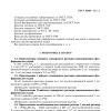
First you need to unscrew the rail, which is screwed with two bolts (see photo above). Unscrewed? We put it aside, we will still need it.

Now notice the 2 bolts near the head cleaning mechanism. We also unscrew them. However, on the left side it is done a little differently, where you can cut off the fasteners.
To remove the entire platform with the head, first, carefully inspect everything and mark with a marker those places where it will be necessary to cut the metal. And then carefully cut the metal with a hand grinder (Dremel, etc.)


Step 4: Cleaning the print head
This step is optional, but since the printer has been completely disassembled, it's best to clean the print head right away. Moreover, there is nothing complicated in this. For this purpose, I used ordinary ear sticks and glass cleaner.

Step 5: Installing the Printhead Platform Part 1
After everything is disassembled and cleaned, it is time to assemble the printer, taking into account the necessary clearance for printing on textolite. Or as the jeepers say "lifting" (i.e. lifting). The amount of lifting depends entirely on the material you are going to print on. In my modification of the printer, I planned to use a steel material feeder with textolite attached to it. The thickness of the material supply platform (steel) was 1.5 mm, the thickness of the foil textolite, from which I usually made boards, was also 1.5 mm. However, I decided that the head shouldn't press too hard on the material, so I chose around 9mm for the gap. Moreover, sometimes I print on double-sided textolite, which is slightly thicker than single-sided.

In order to make it easier for me to control the level of lift, I decided to use washers and nuts, the thickness of which I measured with a caliper. Also, I bought some long bolts and nuts for them. I started with the front feed system.
Step 6 Installing the Printhead Platform Part 2

Before installing the print head platform, small jumpers must be made. I made them from the corners, which I sawed into 2 parts (see photo above). Of course, you can make them yourself.


After, I marked the holes for drilling in the printer. The bottom holes are easy to mark and drill. Then, immediately screwed the brackets into place.

The next step is to mark and drill the upper holes in the platform, this is somewhat more difficult to do, because. everything should be on the same level. To do this, I put a couple of nuts at the docking points of the platform with the base of the printer. Using a level, make sure the platform is level. We mark the holes, drill and tighten with bolts.


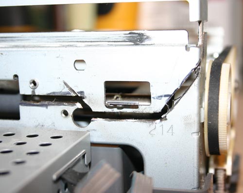
Step 7 "Lifting" the print head cleaning mechanism
When the printer finishes printing, the head is "parked" in the head cleaning mechanism where the head nozzles are cleaned to prevent them from drying out and clogging. This mechanism also needs to be raised a little.
I fixed this mechanism with the help of two corners (see photo above).
Step 8: Feed System
At this stage, we will consider the manufacturing process of the supply system and the installation of the material supply sensor.

When designing the feed system, the first problem was the installation of a material feed sensor. Without this sensor, the printer would not function, but where and how to install it? As the paper passes through the printer, this sensor tells the printer controller when the top of the paper passes, and based on this data, the printer calculates the exact position of the paper. The feed sensor is a conventional photo sensor with an emitting diode. When passing paper (in our case material), the beam in the sensor is interrupted.
For the sensor and feed system, I decided to make a platform out of plywood.

As you can see in the photo above, I glued several layers of plywood together in order to make the feed flush with the printer. In the far corner of the platform, I fixed the feed sensor through which the material will pass. In the plywood, I made a small cut to insert the sensor.


The next task was the need to make guides. For this, I used aluminum corners, which I glued to plywood. It is important that all angles are clearly 90 degrees and the guides are strictly parallel to each other. As a feed material, I used an aluminum sheet, on which copper-plated textolite will be laid and fixed for printing.


I made the material feed sheet from an aluminum sheet. I tried to make the sheet size approximately equal to A4 format. After reading a little on the Internet about the operation of the paper feed sensor and the printer as a whole, I found out that for the printer to work correctly, it is necessary to make a small cutout in the corner of the material feed sheet so that the sensor works a little later than the feed rollers start spinning. The length of the cut was about 90mm.

After everything was done, I fixed a regular sheet of paper on the feed sheet, installed all the drivers on the computer and made a test print on a regular sheet.
Step 9: Refill the ink cartridge

The last part of the printer modification is devoted to ink. Conventional Epson ink is not resistant to chemical processes that occur during etching of the printed circuit board. Therefore, special ink is needed, they are called Mis Pro yellow ink. However, this ink may not be suitable for other printers (non-Epson), because. other types of printheads may be used there (Epson uses a piezoelectric printhead). The online store inksupply.com has delivery to Russia.

In addition to ink, I bought new cartridges, although of course you can use the old ones if you wash them well. Naturally, to refill the cartridges, you will also need an ordinary syringe. Also, I bought a special device for resetting printer cartridges (blue in the photo).
Step 10. Tests

Now let's move on to the print tests. In the design program, I made several blanks for printing, with tracks of various thicknesses.


You can judge the quality of the print from the photos above. Below is a video of the print:
Step 11 Etching
For etching boards made by this method, only a solution of ferric chloride is suitable. Other etching methods ( blue vitriol, hydrochloric acid, etc.) can corrode Mis Pro yellow ink. When etching with ferric chloride, it is better to heat printed circuit board using a heat gun, this speeds up the etching process, and so on. less ink layer "sits down".

The heating temperature, proportions and duration of etching are selected empirically.