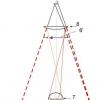
1-outer case;
2-low pressure rotor;
3-inner case;
4-high pressure rotor;
5-intermediate body;
6 attachment points to the aircraft.
Aircraft engine mount.
The engine is mounted on the aircraft, as well as the suspension of the units during transportation, is carried out by means of special fasteners installed on the power housing of the engine. In the general case, the attachment points to the engine transmit loads:
- jet thrust
- Forces of inertia of the masses of the engine, arising from the maneuvers of the aircraft
- Gyroscopic torque from the motor rotor
- Forces of inertia and moment arising from the unbalance of an engine balanced with a certain degree of accuracy.
In addition, a reactive moment from the propeller acts in the theater, directed in the direction opposite to rotation. If the engine has two propellers rotating in opposite directions, the reactive torque is equal to the difference in the torque of the propellers. The design and location of the attachment points on the engine are subject to the following basic requirements:
- The suspension points must be positioned to support the engine in six directions: axial, vertical, lateral, and longitudinal, vertical, and horizontal. In this case, the suspension system must not allow double fastening in the direction and around the named axes. Due to this, the engine housing system is isolated from deformation of the aircraft structure and the occurrence of large off-design loads in the suspension units is prevented.
- The engine mounting points under all flight conditions and operating modes should not interfere with thermal deformations of the engine casing.
- The main suspension points should be located on the power housings of the compressors in a cavity close to the center of mass of the engine. Usually such planes are the planes of internal force connections of the compressor rotor supports.
- Additional suspension points must be located on the turbine housing, as well as in the plane of the internal connections of the turbine supports.
- The afterburner must have an additional suspension point in the plane of the body of the controlled jet nozzle, and the afterburner must also be attached to the turbine body by means of a swivel joint.
- In the case of thin-walled hull structures, in order to avoid large and local radial deformations and grazing of the blades on the hull, large radial forces are not allowed at the suspension points.
- For rigging, assembly and transport work the engine must have additional suspension and support points that meet the requirements for the main suspension points. By doing installation work on an airplane, suspension and support of the engine at arbitrary points is not allowed to avoid deformation.
Design of axial compressors.
Classification of axial compressors.
All compressors can be divided into supersonic and subsonic. In addition, the compressors are divided according to the number of rotors into single-rotor one-stage, two-rotor two-stage and three-rotor.
Two-rotor compressors are arranged in series. Three-rotor compressors are used in double-circuit turbojet engines. They are driven by three gas turbines.
Compressors are divided according to the design of the rotor into disk, drum and drum-disk type.

According to the design of the flow part, the compressors are: with a constant average diameter, with a constant outer diameter and a changing bushing diameter, with a constant bushing diameter and a changing outer diameter.
The compressor consists of a rotor and a stator. On the stator there are blades of straighteners and guide vanes, which change the direction of the flow. The rotor blades are located on the rotor, which rotate to compress the air flow.
compressor rotor.
According to the design, the rotor of an axial compressor can be drum, disk and mixed type. On a rotor of this type, several rows of rotor blades are mounted on a cylindrical or conical drum, which is a groove made of aluminum alloy or steel, machined on all sides. Two steel covers cover the drum from the ends and have trunnions with which the rotor rests on the bearings. The torque of each of the turbines is transmitted through the wall of the drum. The advantage of the drum-type rotor is the simplicity of design, which determines the relative ease of its manufacture and the high transverse rigidity, due to which the critical speed is very high. The critical speed is the speed at which the rotating rotor has large deflections that cause the engine to vibrate and destroy it. The disadvantages of such a rotor include the impossibility of its use in high-speed compressors, due to the fact that on its surface, due to strength conditions, a circumferential speed of no more than 200 m/s is allowed, and also due to the fact that it has a large mass and dimensions. Rotors of this type were used on the first engines, they are not currently used.
The disk-type rotor has specially designed disks connected to the shaft, on the periphery of which the working blades are attached. The discs are highly accurate and allow circumferential speeds of 250-360 m/s on their outer surface, so compressor stages with disc rotors are high-pressure and are used in engines with high pressure ratios. The torque of each stage is transmitted through the shaft. The disadvantage of this type of rotor is the small transverse rigidity compared to the drum-type rotor. The critical speed is not high and close to the working one. The disk-type rotor, in comparison with the drum-type rotor, has a small design and technological complexity.

5-conical belts.
Drum-disk type rotors combine the advantages of drum and disk type rotors. They consist of sections, which are a disk with a drum spacer. Drum-disk rotors have high flexural rigidity, allowing high circumferential rotational speeds, so they are widely used in modern axial compressors. Rotors of a drum-disk design are non-separable and collapsible. Each design has its advantages and disadvantages, for example, the compressor rotor, in which the disks are connected using pins.
|
|

1- disk of the 1st stage;
2- working blade;
3- discs of intermediate stages;
4- pins;
5 - rear trunnion web.
In this case, the rotor section is a disk with a drum section, which is connected to a similar disk by radial pins and an interference fit along the cylindrical belts. Such a connection has the following features: steel pins are pressed into holes located in the grooves of the blades. This ensures the fixation of the pins from falling out under the action of centrifugal forces. With the help of the same pins, torques are transmitted, the drum parts of the disks are centered in the bores of adjacent disks. The described design is characterized by high rigidity and reliable centering of the connected elements. This is explained by the fact that the disks are connected and centered on the maximum possible diameters with relatively large interference. In this design, even in the event of loss of interference or its transformation into a gap, centering is reliably ensured by pins. However, the implementation of disks with drum sections complicates the technology of their manufacture, although this design has relatively few connecting joints. This increases the rigidity of the rotor, making it lighter. The main disadvantage of rotors of this design is the difficulty of mounting and dismounting, because it is essentially a one-piece construction.
Another type of connection very often used in engines is the connection of discs using end slots and a coupler bolt.
|
|

2-rear trunnion;
3-face slots;
4-tie bolt.
End splines made at the ends of the drum sections of a triangular profile. The splines transmit torque and center the discs relative to each other. To improve the fit of triangular splines during assembly, the mating parts are pre-compressed under a press with considerable force in order to remove microroughnesses on the contact surface. The tightening of the bolt is also carried out under pressure and is controlled by the drawing of the bolt. This design is characterized by reliable centering on relatively large diametrical dimensions. This design is collapsible and allows you to easily replace the discs. The disadvantages of such a rotor is the technological complexity of the implementation of the triangular end splines and disks with drum sections, as well as the complexity of installation due to the need to tighten the rotor under pressure. From operating experience, it has been established that on the rotor of this design in transient modes of engine operation (starting, accelerating, braking), a temperature difference appears between the disks and the coupling bolt, because, for example, when starting the engine, the disk pack heats up faster than the coupling bolt. This increases bolt tightness, and vice versa, when the engine is turned off, the disc pack cools faster than the tie bolt, so the bolt tightness is loosened. It follows from this that the tie bolt experiences large stresses, because its initial tightening must compensate for all kinds of temperature deformations, and the fatigue stresses of the tie bolt cause serious consequences, therefore, in modern engines disc connections are used with fitting bolts. The disks of such rotors have thin-walled drum sections with flanges. The flanges are connected to each other by means of an intermediate disk, on the canvases of these disks there are annular platforms along which the flanges of the drum sections are pulled together with the help of tight bolts that transmit torque and ensure alignment. The rear trunnion of the rotor is connected to the last disc in the same way, i.e. with the help of fitting bolts, the front pin is made integral with the disc. The spread of this design is explained by the following advantages of the rotor of this design: high rigidity, reliable centering, in all engine operating modes, ease of replacing discs. Breakage of one or more bolts does not lead to serious malfunctions. The disadvantages of these rotors include the dependence of the stability of the connection on the bending stiffness of the flanges of the drum devices. Loading bolts with shear stresses with the possibility of relative movement of the connected disks. In addition, there is a technological complexity: the installation of tight bolts is not possible if the holes are not deployed together. In addition, the presence of drum devices that are made in conjunction with disks complicates the manufacturing technology, because. the complex grooving of the discs makes it difficult to ensure proper physical and mechanical properties surfaces in radial and axial directions. Rotors of low and high pressure compressors of the AL-31F engine of a drum-disk design using the latest technologies assemblies. Each rotor consists of a non-separable part, sections that are interconnected by welding, and a collapsible section, which are connected using fitting bolts and ties. This ensures, with an appropriate modular design of the compressor, the maintainability of the rotors in the field.
Working blades.
The rotor blade is the most important part of the rotor, on the perfection and durability of which the reliable operation of the compressor depends. The blade works in difficult conditions, it is affected by inertial and aerodynamic forces. These forces cause tensile, bending and torsion stresses. In addition, the working blades of the last stages are affected by heat about 1000 K. Therefore, the working blade of the compressor rotor must provide:
- High strength and rigidity.
- High degree of purity of processing. This is necessary to reduce friction losses during the flow of air through the interscapular channel.
- high precision execution of dimensions in the manufacture of blades, because the parameters of the air flow in the flow part of the compressor depend on this.
- Possible smaller stress concentrators, especially at the transition points of the profile part to the shank.
- Minimum shank weight. For example, a 1% weight reduction reduces the rotor weight per blade by 4-5%.
- The design of the shank should allow convenient assembly of the rotor and replacement of the blade in case of damage.
- Minimum residual stress. The necessary durability of the blade is determined by the purpose aircraft for which the compressor is intended.
The working blade consists of a profile part (blade blade) and a shank. The shapes and dimensions of the profile part of the blade are determined by aerodynamic calculations. The final design is specified taking into account the requirements for ensuring static and dynamic strength. The working blade should be light and sufficiently manufacturable, allowing mass production. The compressor blade is made with a thin inlet edge and small flow angles. Blade shanks are of three types:
- Dovetail
- Christmas tree
- Articulated.
The profiles of the grooves for the blades in the rotor disks are made the same. When connecting the blade shank with the groove, a lock is formed for attaching the blades. The blade-disk connection must meet the following requirements:
- High strength
- the possibility of placing the required number of blades on the disk;
- ease of assembly and replacement of blades;
- small mass.
The most widely used connection type dovetail. The cross section of the blade is made in the form of a trapezoid with flat working surfaces. The groove in the disc is also a trapezoid, which is placed at some angle to the rotor axis.
|
|

The dovetail connection has the following advantages:
- It differs not in high height, this allows the use of light discs;
- has a relatively small thickness, this makes it possible to place the required number of blades on the disk in order to obtain a grate of the desired density;
- design manufacturability.
A significant disadvantage is the low ability to dampen the oscillations of the blades, as a result of the oscillations of the blades, alternating contact stresses appear, which cause the destruction of the shank or the protrusion of the disk.
The spruce connection is practically not used in compressors due to the complexity of production.
The hinged mount of the blades is as follows:
|
|

4-rivet;
5-blade.
In the above diagram, the blade 5 is inserted into the grooves of the disk 1 with the lugs of the locks and is connected to the disk with the help of fingers 3. From axial movement, the fingers are limited on one side by radial protrusions, and on the other side with the help of a washer 2 fixed with a rivet 4.
The swivel joint allows the blade to self-align under the action of gas-dynamic and inertial forces on it. Such a blade can be used at moderate circumferential speeds at the periphery of the blades of approximately less than 320 m/s. A solid lubricant is used to reduce wear and eliminate sticking in the joint. In the lugs of the blade from the inside, from the ends and outer surface the axis is rubbed with molybdenum disulphide powder.
Compressor housing.
The compressor housing is a hollow cylinder or a truncated cone, depending on the method of profiling the compressor flow path. Front and rear bearing housings are attached to the compressor housing from the ends.

The compressor housing can be one-piece and split, with a longitudinal split or a transverse split. The longitudinally split housing allows the compressor to be assembled with the rotor completely assembled and balanced. If the housing is not detachable, then the rotor together with the guide vanes is inserted from the end. In some cases, technological connectors are made, for example, transverse technological connectors are used in the manufacture of housings from different materials. For example, aluminum alloy is used for the first steps, steel alloys are used for the last ones. Flanges used to connect parts of the body to each other increase rigidity and reduce the bending work of the body. However, the non-uniform rigidity of the split housing around the circumference leads to uneven thermal expansion and warping when heated, therefore, ribs are usually installed on the outside of the housing, with the help of which the same rigidity around the circumference is achieved. Compressor housings are cast from aluminum alloys or welded from sheet steel and titanium alloys. The compressor casing usually consists of a front casing, several intermediate casings and a rear casing. An inlet guide vane is installed in the front housing, which changes the direction at the inlet.
|
|

1-threaded trunnion;
3, 5-half rings;
4-inner trunnion.
Guide vanes are installed on the intermediate housings and the rear housing. In addition, the rear housing serves as a power connection with the combustion chamber housing, so it is made of a more heat-resistant material. The compressor guide vane is mounted on the intermediate housings and is an annular set of profiled blades that are installed behind the corresponding stages of the working blades. They can be cantilevered on one side or on both sides. A number of special requirements are imposed on the design of the guide vane, for example, the guide vane must ensure the freedom of thermal expansion of the blades. In addition, it is required that the concentricity of the internal and external fasteners relative to the rotor axis be maintained. In most cases, there are guide vanes with double-sided fastening of the blades. The double-sided fastening of the blades can be rigid when the blade is rigidly attached to the outer casing and the inner ring. Such blades are usually installed in the first stages of compressors, where the air temperature changes little. At the last stages of the compressor, guide vanes are installed, which allow radial movement of the blade along the radius during heating. This is necessary to compensate for the deformation temperatures at the last steps. In addition, an air bypass device is attached to the compressor housing.

Air bypass valve:
2-valve body;
3-piston;
4-oil supply fitting;
5-oil drain fitting;
6-spring;
7-protective mesh.

Bypassing air from the compressor using a tape:
1-windows in the compressor case;
2-power cylinder of the bypass mechanism;
3-piston;
4-spring;
5-piston rod;
6-tooth sectors;
7-bypass tape;
8-compressor housing.
Bypass air can be carried out with the help of tape and valves. On the compressor housing there are windows that are closed with bypass tapes. If it is necessary to open the windows, then the tension of the tape is weakened with the help of gear train and air is passed through. In addition, there is an air bypass valve that bypasses air on an executive command supplied through the control system.
Turbojet aircraft engine AL-31F.
Developer: NPO Saturn (under the direction of A.M. Lyulka)
Country: USSR
Trials: 1977
Series production: 1981
AL-31F (“product 99”) is the base engine of a series of aircraft high-temperature bypass turbojet engines with afterburners. Developed under the direction of A.M. Lyulka at NPO Saturn. Engine design began in 1973, the first tests took place in 1977, state tests were completed in 1985. Since 1981, AL-31 engines have been produced at UMPO (Ufa) and MMPP Salyut (Moscow). After the death of A.M. Lyulka in 1984, the work on the engine and its modifications was headed by General Designer V.M. Chepkin. At present, OKB im. Lyulki (Moscow) is part of UMPO.
AL-31F is a basic two-circuit twin-shaft turbojet engine with mixing of flows of the internal and external circuits behind the turbine, an afterburner common for both circuits and an adjustable supersonic all-mode jet nozzle. The engine is modular.
It consists of a 4-stage low-pressure axial compressor with an adjustable inlet guide vane (VNA), a 9-stage high-pressure axial compressor with an adjustable VNA and guide vanes of the first two stages, high and low pressure turbines - axial single-stage; blades of turbines and nozzle devices are cooled (film cooling). The main combustion chamber is annular.
Titanium alloys (up to 35% of the mass) and heat-resistant steels are widely used in the engine design. Turbine blades have cavities in the form of labyrinths, for cooling gases are supplied from the disk to the blade and pass through the holes along the edges (film air cooling), a fir-tree type shank is used to attach the blade to the disk. After the turbine, an 11-blade mixer is installed. To ensure the stable operation of the FC, a turbine spinner is installed, smoothly transferring the flow from an annular to a circular section, with anti-vibration holes, and anti-vibration longitudinal screens are installed in the afterburner.
The engine has an electric ignition system. The launch system can start the engine both on the ground and in flight. To start the engine on the ground, a starting device is used located in the remote engine box. During normal engine operation, the cooling of the turbines is partially switched off to save fuel.
The use of adjustable VNA KND and KVD gives a higher resistance to surge, in practice this meant that the engines would remain operational when the aircraft got into a tailspin and when missiles were launched. The engine in flight can be used in all modes without restrictions. The pickup time from the idle mode to the "maximum" mode at low altitude is 3-5 s, at medium altitude 5 s, at high altitude 8 s. Maximum rotational speed 13,300 rpm.
The engine runs on aviation kerosene grades T-1, TS-1, RT.
It was exported to India and China. Overhaul carried out on aircraft repair plant No. 121 in Kubinka.
Modifications:
AL-31F - basic. Mounted on Su-27, Su-27UB, Su-30, Su-34, Su-35. Initially, the assigned resource of the serial AL-31F was only 100 hours, while the Air Force required 300 hours, but then over time it was brought up to 1500 hours.
AL-31K - engine for carrier-based aircraft Su-33. Afterburner thrust increased to 13300 kgf. Differs in additional anticorrosive protection.
AL-31FM1 - modernized. Afterburner thrust increased to 13,500 kgf. With a four-stage low-pressure compressor KND-924-4 with a diameter increased from 905 to 924 mm, providing 6% greater expense air, as well as a more advanced digital system automatic control(compression ratio 3.6). The temperature of the gases in front of the turbine for this engine is increased by 25°C. The engine is double-circuit, the first circuit passes through the “jacket” for cooling, then it is mixed after the turbine with the hot second two-shaft circuit. It has been mass-produced since 2006 for the Su-27 family of fighters, is installed without modifications in any fighters, including early years of production, installed on 1 Su-27SM / SM2 regiment and are already being installed on the Su-34s being produced.
AL-31FM2 - forced up to 14000 kgf. It features a three-stage low pressure compressor. The assigned resource of the upgraded engine exceeds 3,000 hours. It does not require modification of the aircraft side when installed on aircraft such as the Su-27, Su-30, Su-34, unlike engines of other series.
AL-31FM3 - forced. 3rd stage of modernization of the AL-31F MMPP Salyut, a new three-stage LPC with wide-chord blades of spatial profiling and an increased pressure ratio of up to 4.2 (KND-924-3) is additionally installed, which makes it possible to increase thrust up to 15,300 kgf (obtained at static tests). The blades and disk of a 3-stage HPC are a single unit (blisk), instead of 9 HPC stages, it is planned to reduce the number to 6.
AL-31FP (AL-31FU) - with a rotary nozzle. Developed in 1988-1994. Weight increased by 110 kg, length - by 0.4 m. Installed on the Su-33KUB, Su-37. The main difference from the basic AL-31F engine is the controllable thrust vector, which significantly increases the maneuverability of the aircraft. The vector change is possible at an angle of up to ±16° in the vertical plane and up to ±15 in any direction. “FP” means afterburner rotary. The engine was developed at NPO Saturn and is manufactured at UMPO. AL-31FP engines are installed on 4++ generation fighters - Su-35.
R-32 - boosted AL-31F engine for the record-breaking P-42 aircraft, created on the basis of the Su-27. Afterburner thrust of the engine was increased to 13600 kgf.
AL-31FN - with the lower location of the gearbox. Developed by order of China.
Engine AL-31FP.
.
List of sources:
Wings of the Motherland. No. 8 for 1999. Ufa motors.
Magazine "Engine". No. 3 for 2000. V.M. Chepkin. Masterpiece of the twentieth century.
Photo archive of the site russianplanes.net
AL-31FP
AL-31A series 3
AL-31FN
AL-31F-M1
AL-31F-M2
R-32
AL-31ST
characteristics
AL-31- a series of aviation high-temperature turbojet bypass engines with afterburners, developed under the leadership of A. M. Lyulka at NPO Saturn. The name stands for Arkhip Lyulka, "F" - afterburner, at the AL-31 plant it is called Product 99. Engine design began in 1973, the first tests took place in 1977, and state tests were successfully completed in 1985. Since 1981, AL-31 engines have been produced at UMPO (Ufa) and MMPP Salyut (Moscow). After the death of A. M. Lyulka in 1984, the work on the engine and its modifications was headed by the general designer V. M. Chepkin. At present, OKB im. Lyulki is part of NPO Saturn.
The estimated cost of one AL-31F engine (as of 2008) is 96.4 million rubles.
Design features
AL-31F - Basic two-circuit twin-shaft turbojet engine with mixing of flows of the inner and outer circuits behind the turbine, an afterburner common for both circuits and an adjustable supersonic all-mode jet nozzle. The engine is modular.
It consists of a 4-stage low-pressure axial compressor with an adjustable inlet guide vane (VNA), a 9-stage high-pressure axial compressor with an adjustable VNA and guide vanes of the first two stages, high and low pressure turbines - single-stage axial; blades of turbines and nozzle devices are cooled. The main combustion chamber is annular. Titanium alloys (up to 35% of the mass) and heat-resistant steels are widely used in the engine design. Turbine blades have cavities in the form of labyrinths for cooling from the inside; a Christmas tree-type shank is used to attach the blade to the disk. The rotors are attached to the shaft using roller bearings.
The engine has an electric ignition system. The launch system can start the engine both on the ground and in flight. To start the engine on the ground, a starting device is used located in the remote engine box. During normal engine operation, the cooling of the turbines is partially switched off to save fuel.
The use of VNA gave high resistance to surge, in practice this meant that the engines would remain operational when the aircraft entered a tailspin. The engine in flight can be used in all modes without restrictions. The pickup time from the idle mode to the maximum mode at low altitude is 3-5 s, at medium altitude 5 s, at high altitude 8 s. Maximum rotational speed 13,300 rpm.
Modifications
On the basis of AL-31F developed a large number of modifications.
AL-31F
The basic version of the engine is used on Su-27 fighters and its modifications. The temperature of the gases in front of the turbine is 1665 K. Initially, the assigned resource of the serial AL-31F was only 100 hours, while the Air Force required 300 hours, but then over time it was brought up to 1500 hours. The overhaul life at maximum operating modes ranged from 5 to 15 hours. The maximum number of start-up cycles (TAC) is 300.
AL-31FP
The main difference from the basic AL-31F engine is thrust vector control, which significantly increases the maneuverability of the aircraft. The vector change is possible up to ±16° in the vertical plane and up to ±15° in any direction. The engine was developed at NPO Saturn and is manufactured at UMPO.
AL-31FP engines are installed on 4++ generation fighters: some modifications of the Su-30 and Su-37.
R-32
Uprated AL-31F engine for the record-breaking P-42 aircraft, based on the Su-27. Afterburner thrust of the engine was increased to 13600 kgf.
AL-31F series 3
Variant of the AL-31F engine for the carrier-based Su-33 fighter. Unlike the basic AL-31F, an additional mode (OR) with a thrust of 12800 kgf appeared, which is briefly used when the aircraft takes off from the deck with a full combat load or during an emergency go-around.
AL-31FN
Modification of the AL-31F with the lower arrangement of the gearbox for the Chinese fighter Chengdu J-10. It has a traction force increased by 200 kg compared to the basic version. Developed at MMPP Salyut, from 2009 300 engines will be delivered under two contracts.
The R&D contract between China and Russia was signed in 1992, and funding was also provided by China. In 1994, the engine was finally designed.
Initially, the engine was developed jointly by NPO Saturn with MMPP Salyut, but after 1998 MMPP Salyut developed documentation and adjusted mass production AL-31FN independently. In 1999, under the Ministry of Justice, federal agency for the Protection of the Results of Intellectual Activity (FAPRID). In an effort to delegitimize developer rights, CEO MMPP Salyut Yuri Eliseev managed to sign a license agreement with FAPRID (No. 1-01-99-00031), which became the very first agreement of this kind concluded by the newly created agency. Referring to it, Salyut considers the 1998 license agreement with Saturn as void.
AL-31F-M1
Upgraded engine AL-31F MMPP Salyut with a four-stage low-pressure compressor KND-924 with a diameter increased from 905 to 924 mm, providing 6% more air consumption, as well as a more advanced digital automatic control system. The temperature of the gases in front of the turbine for this engine is increased by 25°C. The engine is double-circuit, the first circuit passes through the "jacket" for cooling, then it is mixed after the turbine with the hot second two-shaft circuit.
The first flight on January 25, 2002, has been mass-produced since 2006 for the Su-27 family of fighters, is installed without modifications in any fighters, including early years of production, installed on the 1st regiment of the Su-27SM / SM2 and are already being installed on the Su-34s being produced . Adopted by the Air Force of the Russian Federation in 2007. It has an increased thrust force by 1000 kgf (13,500 kgf), an overhaul life of 1000 hours, an assigned resource of 2000 hours while maintaining overall dimensions and weight. Specific fuel consumption has been reduced. It has a modification with a controlled thrust vector, with a resource of 800 hours.
- Length 4.945 m
- Maximum outer diameter 1.14 m
- Weight 1520 kg
AL-31F-M2
The AL-31FM2 engine is a bypass turbojet engine based on the AL-31F. Blades with perforation along the edges are made by casting, the temperature before entering the turbine is increased by 100°C compared to Al-31F. Engine thrust in special mode 14,300 kgf, in full afterburner mode 14,100 kgf. The assigned resource of the upgraded engine exceeds 3,000 hours. The engine has minimal differences from the 3, 20 and 23 series. unit costs fuel, including in afterburner modes. It does not require modification of the aircraft side when installed on aircraft such as the Su-27, Su-30, Su-34, unlike engines of other series. In 2012, the engine is planned to be put into flight tests.
File:AL-31m2
AL-31F-M3
3rd stage of modernization of AL-31F MMPP Salyut, a new three-stage LPC with wide-chord blades of spatial profiling and an increased compression ratio up to pk = 4.2 is additionally installed, which allows increasing thrust to 15,300 kgf (obtained in static tests). Blades and disc are one piece. Since 2002, the engine has been on bench tests.
AL-41F1
The engine of the "first stage" for a promising fifth-generation aviation complex with a thrust of 15,000 kgf. Created on the basis of the AL-31F, AL-31FP and AL-41F engines. Despite the scheme similar to the AL-31F, the engine consists of 80% new parts. It is distinguished from its predecessors by increased thrust (15000 kgf versus 12500 for the AL-31F), completely digital system controls, a plasma ignition system, a new larger-diameter turbine, a significantly increased service life (4000 hours versus 1000 for the AL-31F) and improved consumption characteristics.The development cost amounted to 3 billion rubles.
AL-31ST
"Ground" stationary modification AL-31F with a capacity of 16 MW for use as a drive for gas pumping stations.
On the base Federal State Unitary Enterprise "SPC Gas Turbine Engineering" Salyut» a scientific and technical council was held dedicated to the results of development work on the modernization of the AL-31F engine of the second stage (AL-31F M2). The Sukhoi Design Bureau is interested in a product for the further remotorization of the Su-27SM and Su-34 aircraft in service with the Russian Air Force.
The Scientific and Technical Council, which was attended by all interested parties - representatives of the Sukhoi Design Bureau, NTC im. Lyulka, United Aircraft Corporation and United Engine Corporation, was held for the first time in the last five years. Sergei Rodyuk, head of the department of leading designers, made a report on the results of the work achieved during the modernization of the AL-31FM2 engine of the second stage.
All work related to the second stage of engine modernization is carried out in accordance with the given schedules. To date, special bench tests of the engine of the second stage in the CIAM thermal chamber have been completed, which confirmed the possibility of achieving a static thrust of 14,500 kgf and ensuring the declared characteristics in flight. Compared to the AL-31FM of the first stage, the flight thrust was increased by 9%.
“Modernization of the AL-31F engine is carried out without changing its overall dimensions and is aimed at maintaining the possibility of re-engining the entire Su-27 aircraft fleet without additional changes aircraft airframe or engine nacelle,” said Gennady Skirdov, acting general designer of Salyut.
By the end of 2012, it is planned to complete the program of special bench and life tests, as well as to begin the implementation of the program of special flight tests preceding the state special tests.
According to Vladislav Masalov, Director General of the Salyut Research and Production Center for Gas Turbine Engineering, serial deliveries of the upgraded engine can be started as early as 2013. “The AL-31F M2 engine can be considered as an inexpensive option for the remotorization of the fleet of Su-27, Su-30 and Su-34 aircraft operated by the RF Ministry of Defense, as well as for deliveries to foreign customers,” said Salyut's CEO. To meet the requirements of the terms of reference and specifications for the Su-27SM and Su-34 aircraft, it is necessary to use an engine with increased thrust and better costs. The use of the AL-31F M2 engine on these aircraft will ensure that the requirements are met. Its installation will not require any modifications to the aircraft and can be carried out directly in operation.
Brief information:
Engine AL-31FM2- turbojet bypass engine based on AL-31F. Engine thrust in special mode 14,500 kgf. The assigned resource of the upgraded engine exceeds 3,000 hours. The engine has minimal differences from series 3, 20 and 23. Traction characteristics are increased with a decrease in specific fuel consumption, including in non-afterburning modes. Does not require modification of the aircraft side when installed on aircraft such as the Su-27, Su-30, Su-34 instead of engines of other series. Modernization is possible when repairing engines of early series. LTH and performance characteristics The aircraft have been improved by increasing the parameters and eliminating the oxygen supply system. Increased accuracy of regulation and quality of diagnostics.