The article gives the names of English commands and options and, if they are translated, Russian ones in brackets. However, in any localized AutoCAD, you can use the universal notation for commands and options. Universal notation is when to English titles commands and options are prefixed with _ (underscore). For example, to call the command LINE SEGMENT, you can type on the command line _LINE, and to close it - _C(short for _close). If you see such a fragment in the text: "The command for this is vpclip(VEKREZ)", then on the command line you can type either VEKREZ or _Vpclip.
There are two spaces in AutoCAD: model space (Model space) and paper space (paper space). Using two spaces allows you to draw your work in full size, that is, at a scale of 1: 1 in MS, and scale and format the drawing in PS. There are huge benefits to using two spaces, which are described below. However, many people work with only one space, which can only be explained by ignorance of the new features of AutoCAD. As for the two spaces, they appeared in the last century. They are new only for those users whose teachers did not know it themselves. In AutoCAD, with almost every version, new items appear that are tied specifically to the use of two spaces. For example, Sheet set (Filing), expansion of viewports, annotative objects, etc. It turns out that for those who do not work with two spaces, new items pass by. The train is leaving.
There are drawings, for example, in geodesy, some other industries, in which paper space is not specifically used. But this is the exception rather than the rule.
Working in one space, drawings are made in one of the following ways:
- Life size drawing in MS. Everything drawn is drawn together so that it enters the frame. If there are details of a different scale, they are scaled, that is, they are not drawn in actual size. Printing is done from the model to the drawing scale.
- Drawing in MS at full size, but then the entire drawing is scaled so that it enters the normal size frame. All dimensions must have a measurement factor that takes into account the scale. The print is made from a 1:1 scale model. Those who work this way are unlikely to know about the existence of a very useful command. Dist(Distance).
- Drawing in MS at once in scale, as on a drawing board. The frame is here. This method is the most masochistic and we will not dwell on it.
- The entire drawing is drawn in paper space using one of the above methods. Such drawing does not look natural.
There are also users who aggressively argue the benefits of working in a pure model. Their main argument is that working with two spaces is like drawing "through a hole in the fence." Others think that those who use layout(Leaf), in the sheet and draw, and therefore reject the sheet a priori. Apparently, they have seen enough of those who work according to paragraph 4 above.
Here we will try to learn a very old, but new for many, way of making drawings using two spaces. Separate the flies from the cutlets. The drawing will be done in MS and its design in PS.
So, open one of your files, where the drawing was made in MS, re-save it under the name Training. Delete the frame and title block (stamp). Those who have drawn their study drawing in paper space, but life size, must transfer all work to model space (without the frame and die, which are also removed). This can be done like this: Ctrl+X and selecting all objects in paper space and then ctrl+v in model space. The base point - for simplicity - does not matter. We also consider that there are no closed and frozen layers in this drawing.
Now switch to paper space by clicking the button layout(Sheet) at the bottom, under the drafting field on the left. In this space, you can most likely see your drawing on a white background at an unknown scale inside a certain frame, as well as a dotted frame around the perimeter. It's like a sheet of paper with default dimensions. What you see on the screen depends on the settings in the dialog box. Options(Setting) tab display(Screen) in the field layout elements(Sheets). Open the mentioned dialog box (drop-down menu Tools(service), last item) then tab display(Screen). Remove all the birds in the field to simplify layout elements(Sheets) except the first. (In the future, when you master printing from paper space, you will deal with these birds and return some of them. If there was no bird here before, put it so that the buttons appear Model(model) and the button mentioned at the beginning of the paragraph layout(Sheet). Here, change the background color to the same one you are used to working in model space (most often it is black). The dotted box will disappear. Now delete the border that surrounds your drawing. It will disappear along with the frame, but don't worry: the blueprint hasn't gone anywhere in model space. The frame is actually viewport, which will be discussed below. Here, in layout(Sheet), the MS drawing will be arranged so that it can be printed at the correct scale. Now here you should place a drawing frame of the desired size with the main inscription (stamp) on a scale of 1:1. That is, if we are talking about A1 format, then the size of the frame should be 841x594mm. It can be drawn here, copied from another drawing, or taken from Template(template). If you already have desired frame, but enlarged relative to its actual size by as many times as the scale of the drawing, reduce it by the same amount and copy it to paper space, that is, to layout. The frame should be placed so that its lower left corner is at 0,0 coordinates. It is important that the frame is the actual size. This is a fundamental difference from the way in which the drawing frame is placed in MS (or in PS - for those who make the entire drawing here) and at the same time has dimensions increased as many times as the scale of your drawing.
The sheet space can be thought of as an opaque curtain that covers everything that is drawn in the model. Open the curtain: Dropdown menu View >> Viewports >> 1 Viewport. (View >>Viewports >> 1 InScreen). Specify two opposite corners within the drawing frame, for example, the first near the bottom left corner of the drawing frame and the second near the top right. The dimensions of the VE will be specified later. As soon as the VE was formed, the curtain, as it were, moved apart and everything that was drawn in the model became visible through it, but on a random scale. Now you should scale the picture and place it in the drawing frame in the best way. But before that, let's create a layer called Vport, or Vscreen, and drag the VE frame here. In the future, such a layer should be prepared in advance. The main inscription, of course, will also be placed in the layer intended for it, for example, VEFormat
For now, everything inside the VE frame is uneditable. The VE is, as it were, covered with transparent glass. Let's go inside the CE by double-clicking the left mouse button inside it or by pressing the button Paper(Sheet) in the status bar, that is, at the very bottom of the AutoCAD window on the right. Now you have access to objects and you can set them to the desired scale. Let's do it as a team Zoom(Show). Enter the command on the command line, press Enter and write down the same 1/50XP (For English AutoCAD). The picture will take a scale of 1:50. If we wrote 1/20 XP, then the scale would become 1:20. Recording means setting the Zoom of the model so that in PS this model is reduced by 50 times (in the second case - 20 times) compared to its actual size. The sign "X" means multiplication, the English letter "P" is the first letter of the word Paper, Sheet. Thus, the model is zoomed by multiplying by 1/50 (1/20). Next command Pan(Pan), taken better from the button, and not from the mouse wheel, move the model to the correct position relative to the drawing frame and close the CE by double-clicking outside it or by clicking Model(model) in the status bar. The screen can be locked from accidental scale failure. Close the VE, select its frame and in the context menu of the right button select display locked(Show blocked).
If there are details in the drawing that need to be shown at different scales, several VEs should be placed inside the drawing frame and the corresponding detail should be displayed in each at the desired scale, although in model space all the details are drawn in full size. If you need to show an enlarged assembly, part of an assembly drawing or a part, it is not at all necessary to draw a separate fragment. It is enough to bring this node into a larger-scale CE.
This is not possible without using Paper Space.
There is such a thing as off-scale elements. These are called objects, the size of which on paper does not depend on the scale of the drawing. For example, the height of the text, the size of the size details, the ratio between strokes and spaces in non-solid lines, the frequency of hatching, character blocks, and some others. Such elements, when they are drawn in the model, must have values that depend on the scale (recall that with the development of paper space, it becomes possible to collect details in one drawing at different scales, although they are all drawn in natural size). If the normal text height is 3.5mm, then in a model whose section is planned to be printed at a scale of 1:100, the text height should be set to 350mm. For another area printed at a scale of 1:20, the text must be readjusted to a height of 70mm. The dimension style is easiest to set to a scale of 1:1 (with Dimscale= 1) and then, based on this style, create a series of dimension styles for each scale. All of them will differ from the base one only by the value of the system variable Dimscale, always equal to the scale. However, there are other ways of measuring. One of them is shown below, in paragraph 12.
A drawing made in model space and formatted in paper space should be printed at a scale of 1:1, and then its frame will have the correct dimensions, and the contents of the drawing will have the necessary scales specified inside the viewport.
To work with two spaces - model and sheet - AutoCAD has many more options. We list them here, but without a detailed description.
- Scaling inside the CE can also be done through Properties(Properties) or using the dedicated toolbar Viewports(Viewports). Before that, you need to close the CE and select its frame.
- The layer containing the VP frames can be closed ( Off) or freeze ( freeze). Now the frames will not be visible either on the screen or on paper printouts. If this layer is made non-printable (In the dialog box Layer Property Manager column Plot) (Layer properties manager) but do not close or freeze, the frames will be visible on the screen (which is convenient) but they will not be on the printout).
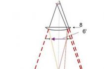
Some users place VEs on a layer called Defpoints, but this is also not a good rule of thumb for AutoCAD. This layer is a service layer and is intended for automatic placement of defining dimension points in it. - You can create a polygonal (shaped) frame of the VE or make it in the form of an object previously drawn with a polyline, circle or even a spline. If the CE already exists, it can be trimmed, that is, its shape can be changed. For this, the command vpclip(Vackrez). All this provides great opportunities in the layout of the drawing.
- VE can be copied, moved, stretched around the corners. Can be copied to another file via clipboard(Clipboard). If you copy the contents of the model at the same time, then it will also appear in the viewport of the drawing where the copies of the object and the CE were transferred. Naturally, the CE should be copied from PS to PS, and details from MS to MS of the second file. The position in space of copies and originals must be the same (for example, copying relative to a single base point of 0,0). Otherwise, you should move the space with the desired object so that the latter fits into the CE frame. Beginners often stumble at this point: A CE copied into another drawing remains empty until you force it to open. The frame of this CE should be selected and from the right-click menu select Display viewpotr objects > Yes.(Visibility of objects on screen > Yes)
- It is possible to create different files in one file with one model. Layouts(Sheets) with their own set of SE, that is, make several drawings from a common model without dividing it into parts. This is indispensable if the model does not fit entirely into the frame of the drawing at an acceptable scale, for example, the floor plan of a large building. It happens that the model is a long and narrow route, for example, a pipeline, a power line or a highway. In the model, the route should be drawn as a whole, without breaking into sections corresponding to the length of the paper drawing. In the first layout(Sheet) you need to create 2-3 (as many as fit on the width of the paper sheet) long and narrow SEs, one under the other, and sequentially draw the next section of the route into each of them in the correct scale. If the track does not fit on one layout(Sheet), here the second and subsequent ones are created. Each one creates its own CEs and each section of the route is started. It is quite obvious that each Layout (Sheet) should have its own frame and title block, but since the next Layout is usually created by copying the previous one, it already has all this, including , stamp partially. Rename layout(Sheet), as well as copy it, create a new one or move it, by selecting the desired action in the right-click menu after clicking on the button layout(Sheet).
- Usually, the drawings of one project have notes, tables, etc. common to several drawings. They are placed inside the drawing frame, repeatedly copied from one drawing to another. When working with Layouts(sheets), which are based on a common model, such objects are placed only once in the model and then in each sheet they are displayed in the right place through their own CE. Thus, it turns out that in Layout there may be nothing but a frame and a stamp.
- Inside the VE, the model space can be expanded. At the same time, the objects drawn in it unfold along with the space. This is not a team Rotate (To turn) that rotates objects in space. Here all space rotates, and objects relative to it remain in their places. For example, a vertical - in the model - facade of a skyscraper can be displayed horizontally in the drawing frame. The invaluable advantage of two spaces - model and sheet!.
To do this, use any of the three commands: Mvsetup options Align then Rotate (Formatl, options align then, To turn) and, after specifying the point of rotation, you should specify the angle), _Dview.with option _Twist (DVID with option Rotate) or command from the menu Express Alignspace
Note: In the program that forms the command Mvsetup(Formatl) in the Russian version of AutoCAD, an error crept in, so it's better to type the command in the English layout like this _Mvsetup. Or correct accordingly. (Corrected by Vladimir Gromov, Moscow) - It is possible in each personal view to freeze the layer in which objects are located that are not intended to be shown here. But they will be visible in other VEs with the same section of the model. To do this, you need to open VE and then Layer Properties Manager(Layer Properties Manager) and in the column Current VP Freeze(Frozen on Current VP) Freeze the given layer. Or, without opening the Layer Properties Manager, do it with the command Layfrz(LayzMr) from the menu Express.
- AutoCAD 2008 introduced annotative objects. For example, one section of the model must be shown on the drawing at different scales, on general plan and, enlarged into details. Let's say there is text in this section. This text can be given a new property - Annotative, and set up so that in the VE of different scales the text is always printed out at the same size, for example, 3.5mm. In the model, the text will have a height depending on the scale. If the scale of the drawing (on paper) is 1:100; then the text height in model space is 350mm.
- In AutoCAD 2008, you can make the same objects in different viewpoints get different colors, linetypes, and lineweights.
- Viewports can be stacked on top of each other for some special purposes. For example, in this way you can apply a solid fill, and it will not cover the objects located in the same place in the plan.
- In newer versions of the VE, you can expand it to full screen and work in the model without fear of losing the scale of the VP. For this, as well as for returning to the initial state, the commands are Vpmax(Wecrmax) and Vpmin(Workmin) as well as the button Maximize viewport(Expand VScreen) on the right side of the status bar. You can also double-click the VOS frame. This button is only visible in paper space when one of the sheets is enabled. In such a full-screen VE, you can draw and set dimensions that will automatically perceive the scale of the VE, if in the dimension style on the tab FIT. (Placement) In the field Scale for Dimension Feature (Scale for dimensional elements), set the switch to Scale dimensions to layout (paperspace) (Scale relative to the sheet).
- When working with only one space, for example, a model, it is necessary to have a set of frames and title blocks for all drawing formats and in each format for all applicable scales. When using two spaces, it is enough to have as many frames as there are formats used in your practice. Because all drawings are printed from paper space in a single 1:1 scale.
- Sheets are easily set up for printing and AutoCAD will remember the settings. Now you can repeatedly output the drawing to the printer with one click of a button. You can create a Sheet Set - a sheet set consisting of all sheets of a given file and send them to the printer with a few mouse clicks. Moreover, the program itself will send each sheet to the desired printing device, if the drawings are multi-format. In the same way, you can assemble drawings from different files into a binder, that is, a whole project. You can select separate scattered sheets of this file for printing and, without opening them, send them to those printers for which they were configured in advance. For this, it is necessary to select desired sheets, pressing Ctrl I and from the right-click menu select Publish selected layouts.
- There is a command that allows you to transfer objects from one space to another, automatically scaling them. This is the team chspace and it's on the menu Express. There are also a number of commands for working with paper space.
- Navigation through viewports, that is, the transition from one to another, can be done either by clicking inside the next viewport, or, if some viewports are inside others, by pressing the buttons ctrl+r on keyboard. The transition from one sheet to another, in addition to the buttons under the field for drawing, can be done by pressing the keys Ctrl+PageUp or PageDn.
- You can create several VEs in model space, but this is not used for drawing design, but for the convenience of working in the model. In particular, you can place a fragment in the model, which should always be in front of your eyes, and display it on a small screen on the side, which is adjacent to the main working field. Or, dividing the screen in half, display different parts of the model in each part. A CE becomes active when you click inside it. The creation of such VEs is carried out in the same way as in paper space.
Most of the above cannot be done without the use of Paper space and Layouts, and those who do not use paper space impoverish their AutoCAD.
When using two spaces, there may be a problem with the display of linetypes: suddenly, on the printout, all dashed lines turn into solid lines. This is due to a mismatch in the scale of the lines in the model and on the sheet.
Scale can be adjusted in one of two ways:
- Open line type manager(Linetype Manager). It's in the drop down menu. Format(Format). Then Show details(include details). Expose global scale factor(Global scale) to the value that the main viewport will have, for example, 100. Uncheck Use paper scale units for scaling(scale in paper space units). Click OK; then in the model do a regeneration. After that, all dashed lines that fall into this viewport will look correct. In other areas of the model that will be displayed in a different scale CE, non-solid lines should be given a personal scale in Properties(properties). If the scale of the SE is 1:50, that is, twice as large as the main scale of 1:100, then all non-solid lines should be scaled to 0.5. The cumulative scales of the lines will equalize and on the printout you can see lines with the same length of dashes and gaps.
The global scale is stored in a system variable Ltscale, and the presence or absence of a bird in the window Scale in paper space units adjusted by system variable Psltscale, which can be either 1 or 0. Thus, you can set the line scales without calling the Line type manager dialog box, but by simply typing the names of these variables on the keyboard.
If you memorize these and a dozen other variables and know how to use them, you will soon become cool autocads and people will come to you for advice. - Expose Ltscale to the value 1 (and not 100, as described in paragraph 1). Psltscale also set it to 1. Now in paper space, the lines will be displayed according to the scales of the viewports. This will be visible in paper space. But in the model, all lines will be visible as solid. Since the work on the drawing is carried out in the model, in this case you have to maneuver, namely, when opening the model, you should set Ltscale to the drawing scale value. Going to the sheet, you should give the variable Ltscale value 1. Actually, this transition can be automated, but this is not the topic of this article.
Vladimir Light
New York, May 2008
Attention! It is forbidden to reprint this article or part of it without the consent of the author. If you would like to publish this article on your website or print it, please contact the author.
You have already learned how to create simple two-dimensional drawings. However, in most cases, the work does not end there, since the results of your work must be prepared for printing and put on paper. How to do this will be discussed later in this chapter.
When working with AutoCAD, you probably already noticed that at the bottom of the graphics area of the drawing, the tab is usually selected Model(Model) (Fig. 8.1).
Rice. 8.1. Building plan in model space
This tab allows you to work in model space, where all drawing objects are drawn and edited. Next to the tab Model(Model) tabs located layout(Sheet) (there are two by default), by activating which we will switch to sheet space. Paper space is an environment designed to host various views of a design drawn in model space. A drawing of the floor plan in paper space is shown in fig. 8.2.

Rice. 8.2. Building plan in paper space
Paper space is used to place several views of the constructed model on one drawing. Working in paper space is similar to working on a drawing board, as any sheet tab mimics a paper sheet.
There are several different elements that can be highlighted on the model space tab. First, it is the virtual sheet of paper itself, which has White color. Secondly, the dashed outline shows the border of the print area. The presence of this area is due to the fact that most printers cannot print near the border of the sheet. Also, one floating viewport is created per sheet by default. Again, paper space viewports are required to display the view of the model.
As noted earlier, by default, when creating a new drawing, two paper space tabs appear at the bottom of the graphics area − Layout1(Sheet 1) and layout2(Sheet 2). However, there may be fewer such tabs, and if you wish, you can also create new sheets. At the same time, individual settings are set for each sheet: dimensions and orientation, default printing device, floating viewport configuration, etc.
Creating and editing sheets
The easiest way to create a new sheet is with Layout Wizard(Composite Wizard). To call it, execute one of the menu commands: either Insert > Layout > Create Layout Wizard(Insert > Sheet > Create Layout Wizard), or Tools > Wizards > Create Layout(Tools > Wizards > Create Layout). The LAYOUTWIZARD command can also be invoked from the command line. In any case, the first window of the layout wizard will appear on the screen (Fig. 8.3).

Rice. 8.3. The first window of the layout wizard
In this window, you need to enter the name of the sheet to be created, which will later be displayed on the corresponding tab. The program suggests the serial number of the new sheet - in our case it is Layout3(Sheet 3). To better navigate the sheets with layouts, enter some meaningful name in this field that would reflect the essence of the drawing contained on this sheet.
Click the button Further, to open the next layout wizard window (Figure 8.4). It is used to select the printing device for the created sheet (configuration of printers and plotters is discussed later in this chapter). Select the desired device by clicking on the appropriate line. If you select the item None(No), no default printing device will be set.

Rice. 8.4. Layout Wizard Printer Setting Window

Rice. 8.5. Layout Wizard Paper Setting Window
In the next window (Fig. 8.6) select the type of title block from the list of files. In area preview(View) schematically shown appearance selected stamp. Element None(None) means no title block. The title block stamp can be included in the drawing as a block by setting the switch to block(Block), or as a link by setting the switch to xref. Better choose a position block(Block), because in this case the title block will be saved in the drawing.

Rice. 8.6. Title block settings window
Advice
Note that the proposed list does not contain stamps corresponding to GOST. Therefore, we recommend that you spend time once creating the desired title block, so that you can simply insert it into your drawings in the future. Once you have drawn your stamp, save it as a .dwg file in the directory<Системный_диск>:\Documents and Settings\<Ваш_профиль>\Application Data\Autodesk\ AutoCAD 2010\R18.0\enu\Template\.
The next window of the wizard is designed to determine the number of viewports on a sheet (Fig. 8.7). With switch viewport setup(Viewport Settings) you can select one of the following layout options.

Rice. 8.7. Viewport settings window
None(None) - Set the radio button to this position if you do not want to create a viewport in paper space. Later, you can define viewports manually.
Single(Single)—One rectangular viewport is created.
Std. 3D Engineering Views(Standard 3D View) - Creates four viewports. It is assumed that three of them will have frontal, profile and horizontal projections, and the fourth screen is necessary for isometric representation of the model.
array(Array) - after setting the switch to this position, the fields at the bottom of the window become available. Here you can set the number of rows and columns of viewports, as well as the distance between them.
In the next window of the wizard, there is only one button - select location(position selection). When you click it, the wizard window is temporarily hidden, and you return to paper space, where you need to determine the size of the area that all viewports will occupy by specifying opposite corners. If you don't press the button select location(Select position), then the viewports will fill the entire plot area.
IN last window layout wizard click on the button Ready, to complete the job of creating a new sheet.
When the wizard finishes, you will be in the space of the layout sheet you just created.
Sheet editing
Right-click on the spine of the tab you are editing. The context menu will open (Fig. 8.8).

Rice. 8.8. Sheet tab context menu
This menu contains the following options.
new layout(New Sheet) - Creates a new sheet tab based on default print device and paper size settings. A new name is assigned to the sheet automatically: for example, when creating the fourth sheet tab, this will be Layout4(Sheet 4).
From template(From Template) - allows you to create a new sheet based on an existing drawing or template. After selecting this item, a dialog box appears on the screen. Select Template From File(Select a template from a file), in which you must specify the location of the file with the extension DWG or DWT. After pressing the button open(Open) closes the current window and displays a dialog box Insert Layout(s)(Insert sheet(s)), where you can select a specific sheet of this drawing. As a result of such an operation, all elements of the selected sheet will be transferred to a new sheet: a stamp block, viewports, etc. However, the objects of the tab Model(Model) will not be imported to the new sheet.
Delete(Delete) - allows you to delete the selected sheet. Before uninstalling, the program will definitely display a warning window. The sheet will be deleted after clicking the button OK.
Rename(Rename) - after selecting this item, the name of the sheet on its spine will be highlighted. To rename a sheet, you must enter a new name and press the key Enter.
Move or Copy(Move or copy) - selecting this command brings up a dialog box of the same name that allows you to create a copy of the current sheet or move it. To move the sheet, enter in the field Before layout(Before Sheet) The name of another layout sheet to the left of whose tab you want to place the current sheet. Selecting an item move to end(move to end), you move the sheet to the far right. Checking the checkbox Create a copy(Create Copy) creates a new copy of the selected sheet, with the number of the copy made displayed in parentheses of the sheet name.
Select All Layouts(Select all sheets) - selects all sheets present in the drawing. You can then perform bulk editing operations on them, such as deletion.
Items Activate Previous Layout(Activate previous sheet) and Activate Model Tab(Activate model tab) make the previous sheet or model space active, respectively.
Page Setup Manager(Page setup manager) - calls the dialog box of the same name, designed to manage page setup.
Plot(Print) - calls the dialog box Plot(Print) in which print settings are made.
Import Layout as Sheet(Import layout as sheet) - allows you to add the created layout to the sheet set.
Export Layout to Model(Export sheet to model) - allows you to export all visible objects from the current sheet to the model space of a new drawing.
Hide Layouts and Model tabs(Hide Layout and Model Tabs) - Hides the paper space and model tabs, allowing you to slightly increase the graphics area. Now you can switch between the image of the model and its layout on the sheet using the button Model(Model)
and buttons with the name of the layout sheet
located in the status bar. By clicking on the button Quick View Layouts(Quick view sheets)
You can specify which specific sheet you want to display (Fig. 8.9).

Rice. 8.9. Quick View Sheets
By right-clicking on one of these buttons and selecting Display Layout and Model Tabs(Show sheet and model tabs), you will return the tabs to their original positions.
Advice
Pressing Ctrl+Page Up toggles between layout tabs and the model tab from right to left, and Ctrl+Page Down toggles tabs from left to right.
The next step after creating a sheet is to change its settings. To bring up a dialog box Page Setup Manager(Page Setup Manager) (Fig. 8.10), select Page Setup Manager(Page Setup Manager) in the context menu of the sheet, or run the command File > Page Setup Manager(File > Page Setup Manager). Interestingly, for one sheet, you can create several sets of parameters.

Rice. 8.10. Page Setup Manager Dialog Box
This window displays the parameters of the sheets available in this drawing. By checking the box Display when creating a new layout(Display when creating a new sheet), you can ensure that the first time you access the created sheet, a dialog box will automatically appear on the screen Page Setup Manager(Page Setup Manager).
Button New(New) allows you to create a new set of parameters. In the window New Page Setup(New Page Setup) that appears after clicking this button, you must enter the name of the setup to be created. In addition, from the list below, you must select the name of the existing set of parameters, the settings of which are most suitable for the one being created. After clicking the button OK dialog box opens Page Setup(Page settings) (Fig. 8.11).

Rice. 8.11. Page Setup Dialog Box
In addition to creating a new set of options, you can import an existing one from another drawing by clicking in the window Page Setup Manager(Page Setup Manager) on the button Import(Import). Button press Modify(Change) opens a window Page Setup(Page Setup), in which you can change some settings of the current sheet.
From the list Name(Name) located in the area printer/plotter(Printer/plotter) windows Page Setup(Page Setup) selects the name of the default printing device.
Drop-down list paper size(Paper Size) is for selecting the paper sizes available for this printer or plotter. In this case, the dimensions and orientation of the sheet are shown in a small figure next to it.
In area plot area(Print area) indicate the area to be printed. By default, the dropdown list is set to layout(Sheet), but you can also choose to print to drawing borders, print to the current screen, or print to a specified frame.
By default, when printing, the drawing is moved as far as possible to the upper left corner. However, you can set the drawing offset along the axes X And Y, by entering the required values in the appropriate fields. Checkbox Center the plot(Center Print) allows you to center the printed object on the sheet.
The scale can be adjusted in the area plot scale(print scale). In particular, from the drop-down list Scale(Scale) select one of the scale factors. You can explicitly specify a scaling factor in the fields below. By checking the box Scale lines(Scale line thickness), you can set the scale for the representation of line thickness. Since the scale is usually specified individually for each viewport, printing from paper space is usually done at a scale of 1:1.
In area Plot style table(Table print styles) indicate the name of the plot style sheet file.
If you called the window while in paper space, then in the area Shaded viewport options(Viewport Color Options) only the list will be active Quality(Quality) in which the image quality is indicated. If you select an item from this list Custom(Custom), then the field will become available DPI, where you can enter the resolution in dots per inch.
Consider the parameters contained in the area Plot options(Print Options). If the checkbox is checked Plot object lineweights(Take into account the thickness of the lines of objects), then the thickness of the lines of the drawing will be taken into account when printing. If some objects or layers in the drawing have been assigned a plot style and the check box Plot with plot styles(Consider plot styles), then these objects will be printed according to the style assigned to them. Checkbox Plot paperspace last(Print Paper Space Last) determines the order in which objects in paper space and model space are printed. If the checkbox is checked hide paperspace objects(Hide paper objects), hidden lines will not be drawn when printing from paper space.
In area drawing orientation(Drawing orientation) select the orientation of the drawing on a sheet of paper using the switch: Portrait(Book) or Landscape(Album). With the checkbox checked Plot upside-down(Print Upside Down) The drawing will be printed upside down on paper.
Save all settings by clicking the button OK. The program will return to the dialog box Page Setup Manager(Page Setup Manager). If necessary, make this set of settings current by selecting it and clicking the button set current(Make current). Click the button close(Close) to return to paper space.
Viewports in paper space
To view a drawing in paper space, you must create viewports. By default, existing layouts already have one viewport. Usually, one viewport is not enough to accurately represent the model, as it requires showing several different views of the structure, or the same view but with different detail. For example, in technical drawings, three-dimensional parts or assemblies are usually depicted as three projections. In addition, several drawings can be placed on one sheet at once, which means that you can create several floating viewports by placing different views on them.
Note
There are two types of viewports in AutoCAD: non-overlapping and overlapping. Non-overlapping viewports can only be created in model space. This chapter only deals with overlapping (floating) viewports that are rendered in paper space.
Floating viewports are real objects that can be edited.
Advice
Since it is usually not necessary to print the borders of floating viewports, they should be created on a separate layer. In the future, turning off this layer will allow you to remove the borders of the viewports from the sheet. Model space objects remain in place. But even if you plan to keep the borders, still create a separate layer for the viewports - this will provide an opportunity for group editing of floating viewports. For example, you can quickly set all borders to the same color by assigning it to this layer.
Most of the operations for creating and editing floating viewports are performed using the group Viewports(Viewports) located on the tab view(Display) ribbon, or toolbar Viewports(Viewports) (Fig. 8.12).
Rice. 8.12. Viewports toolbar
Create floating viewportsTo bring up a dialog box Viewports(Viewports) (Fig. 8.13), while in paper space, click on the button New(New) in the group Viewports(Viewports) tab view Display Viewports Dialog(Show Viewports Dialog Box) on the toolbar Viewports(Viewports). You can also type the VPORTS command. The same result can be achieved by executing the menu command View > Viewports > New Viewports(View > Viewports > New Viewports).

Rice. 8.13. Dialog box Viewports (Viewports)
List standard viewports(Standard Viewports) allows you to select the number of floating viewports and their location on the sheet. At the same time, in the area preview(View) schematically shows the future location of the viewports and the name of each of them. With the selected mode 2D on the list Setup(Mode) in each viewport sets the view of the entire model. If you set the mode 3D, then standard views of the model will be created in the viewports.
Drop Change view to(Change view to) sets the view in a specific viewport. For example, with the selected mode 3D from this list, you can select one of the standard views or set the isometric display of the model.
In field Viewport Spacing(Distance) indicate the distance at which viewports will be located from each other on the sheet. It is clear that this field becomes active only when creating two or more floating viewports.
After completing all the necessary settings, click the button OK. This closes the dialog box and prompts you on the command line:
Specify first corner or
In response, set the first corner point with the mouse or press the key enter, so that the viewports occupy the entire printable area of the sheet. If you set the first point, then the following prompt will appear on the command line:
Specify opposite corner:
Specify the opposite corner of the rectangular area in which all viewports will fit. The specified path will be filled with floating viewports.
Create a floating viewport with a complex shapeYou already know how to create one or more rectangular floating viewports. However, AutoCAD allows you to create irregularly shaped screens, for which you need to click on the button Create Polygonal(Create Polygonal) in a group Viewports(Viewports) tab view(Display) Ribbon or Button polygonal viewport(Polygonal Viewport) on the toolbar Viewports(Viewports). You can also execute the menu command View > Viewports > Polygonal Viewport(View > Viewports > Polygonal Viewport). In this case, the border of the floating viewport will be created from straight and arc segments.
After running the command, a prompt will appear:
Specify start point:
Set the first point. After that, a new request will appear:
Specify next point or :
Continue picking points or choose one of the suggested options:
When you select the Arc option, you can add arc segments;
If you select the Length parameter, then a linear segment of the given length and direction will be drawn;
The Undo option removes the last fragment created.
After specifying the last point, press the key enter, to complete the viewport borders. It is clear that the viewport outline must be closed, so if the last point you pick does not match the start point, the program will automatically draw a line segment to get a closed object.
Creating a floating viewport from an objectAutoCAD allows you to create floating viewports from any closed objects. To convert a closed polyline, ellipse, spline, region, or circle to a viewport, execute the menu command View > Viewports > Object(View > Viewports > Object) or click the button Create from Object(Create from Object) in a group Viewports(Viewports) tab view(Display) Ribbon or Button Convert Object to Viewport(Convert Object to Viewport) on the toolbar Viewports(Viewports). A prompt will appear:
Select object to clip viewport:
Select a suitable closed object. It will immediately be converted to a floating viewport, in which the image of the model will appear.
Editing floating viewportsThe created floating viewport can be moved, resized or deleted after selecting it.
Like other objects, floating viewports can be edited with grips. However, the most interesting feature is redefining viewport bounds using the VCLIP command. This command is invoked by clicking on the button. Clip existing viewport(Crop Existing Viewport) on the Toolbox Viewports(Viewports). This makes it possible to change the shape of the floating viewport according to the new boundaries. To clip the viewport, you must either pick an existing closed loop or create one during the command.
Select the floating viewport you want to clip and then run the VPCLIP command, or first run the VPCLIP command and then, when prompted:
Select clipping object or
specify a closed object to act as the cropping boundary.
If, in response to this prompt, press Enter(that is, select the Polygonal option), then you will be able to create a clipping boundary manually. As with creating a viewport of a complex shape, in this case the clipping border is formed from straight and arc segments.
You can delete a clipping enclosed area using the Delete option, which is available only if the selected floating viewport is clipped.
Working with the Model in the ViewportAfter creating and editing floating viewports, each of them will display the same view of the model. However, in each viewport, you must set up the desired view. To do this, switch from paper space to the viewport, which can be done in two ways.
Double-click in the viewport you want to select.
Click on the button PAPER(Paper) located on the status bar. The button will change its name to MODEL(Model) and one of the floating viewports is activated in the graphics area. To switch to the desired viewport, click on it with the mouse button.
Advice
To sequentially switch between activated viewports, press the key combination Ctrl+R.
The boundary of the activated viewport is highlighted with a thick line.
By switching to one of the floating viewports, we actually find ourselves in model space. Here you can edit or create new objects, as if you were on a tab Model(Model) and therefore changes will be reflected in all viewports.
Let's take a look at the commands provided by the viewport context menu. Select the floating viewport (its borders will be displayed as a dashed line), and then right-click to bring up the context menu (Fig. 8.14).

Rice. 8.14. Viewport context menu
If there are several viewports on a sheet, then most likely they are small and it is not very convenient to work with the model in such small windows. However, you can temporarily expand one floating viewport to cover the entire graphics area. To do this, select Maximize viewport(Maximize Viewport) in the context menu, or simply double-click on the frame of an inactive viewport. An enlarged viewport with a red border will take up the entire graphics area. Here you can perform all the actions that are on the tab Model(Model), however the zoom and pan commands will not change how objects are displayed in the viewport. To minimize the screen, call the context menu and select the item Minimize Viewport(Collapse Viewport).
You can maximize the viewport by running the VPMAX command, and minimize it by running the VPMIN command. In addition, there is a button on the status bar Maximize viewport(Expand Viewport)
pushing the boundaries of the screen, and you can minimize the screen using the button Minimize Viewport(Collapse Viewport)
that appears in its place.
Team Display Viewport Objects(Display objects in viewports) of the context menu provides the ability to enable or disable the visibility of objects in the viewport. Selecting an item no(No), we will remove all objects contained in the current viewport from the screen. Such an operation can be useful if it is necessary to visually unload the sheet space. To return objects to their place, check the box Yes(Yes).
Context menu command Display Locked(Show locked) allows you to fix the scale of the viewport. By default, the scale of each viewport can be changed individually, but if you check the box Yes(Yes), then when you try to scale the image in the viewport, the display scale of the entire paper space will change.
To switch back to paper space, double-click an area not occupied by viewports, or click MODEL(Model) located on the status bar.
Viewport scalingTypically, printing from paper space occurs at a scale of 1:1. Therefore, in order to achieve the correct layout of the drawing, it is necessary to separately set the scale of each viewport. To accurately scale the drawing, you must specify the scale of the viewport in relation to paper space. This scale factor is determined by dividing paper space units by model space units. You can fine-tune the scale using the XP parameter of the ZOOM command. For example, to scale an image to 1:10, enter 1/10XP when prompted for the ZOOM command.
You can also specify the scale of a particular viewport using the drop-down list on the toolbar Viewports(Viewports). After setting the image scale in the viewport, you should lock this scale factor from random changes. To do this, you need to run the command Display Locked > Yes(Show Locked > Yes) in the context menu of the floating viewport.
Controlling the Visibility of Objects Inside a ViewportIn each viewport, you can separately adjust the visibility of layers. For example, in this way you can hide hatching or text that repeats in several viewports.
Double-click in the desired viewport to make it active.
Click the button Layer Properties(Layer properties)
in Group Layers(Layers) tab Home(Main) ribbon or the same button on the toolbar Layers(Layers). Palette will open Layer Properties Manager(Layer properties manager) (Fig. 8.15).

Rice. 8.15. Palette Layer Properties Manager (Manager layer properties), called in mode Layout (Sheet)
Please note that this window is somewhat different from the similar one called from model space (see Figure 2.27). In particular, new columns have appeared that are responsible for the properties of objects inside the edited viewport: VP Freeze(Frozen in PVE), VP Color(Color in PVE), VP Linetype(Line type in PVE), VP Lineweight(Line thickness in PVE) and VP Plot Style(Print style in PVE). The purpose of these columns does not differ from similar ones without the addition VP, with the only amendment that their change is limited to an editable floating viewport.
For example, to make all objects of a layer invisible, click opposite the name of this layer in the column VP Freeze(Frozen in PVE), or, for example, to change the color of layer objects inside the viewport, use the column VP Color(Color in PVE).
The preparation of the sheet for printing at this stage can be considered completed. Consider the printing process itself.
Once you've finished creating and laying out your drawing, you're ready to start setting up your print. The appearance of the printed drawing will depend on several components: the sheet settings discussed above, the attached print table and, of course, the configuration of the printing device itself. Therefore, before turning to printing a drawing, let's consider working with print styles and configuring printers.
Print Styles
Print style is a property of an object that determines how it will be printed on paper. A print style combines a set of object parameters, such as color, line type and thickness, etc. Unlike other properties, a print style may not be used, in which case the program will print the object in accordance with other properties.
Using print styles allows you to more flexibly control the image of objects on the screen and paper. For example, on a monitor, a line is displayed in one color, but when using a print style and drawing a drawing on paper, the color of the line may be completely different. However, the use of print styles does not affect the display of objects on the monitor.
Plot styles can be combined into print style sheets which are stored in special files.
Color-dependent and named plot stylesAutoCAD uses two types of plot styles.
color dependent print styles are inherited from previous versions of the program. When using them, the appearance of an object depends on its color, that is, specific settings are associated with each specific color. A significant disadvantage of this method is that objects of the same color on paper will look the same. For example, you can't make all objects of the same color have different type lines. Color-dependent plot style sheets are stored in files with the .ctb extension.
Using named print styles, the appearance of an object on paper is independent of its color. Each object can be assigned an arbitrary print style. Named plot style tables are stored in files with the .stb extension.
Only one type of print style sheet can be used in a program at a time, either color dependent or named. The type of print style can be selected on the tab Plot and Publish(Print and Publish) Dialog Box Options(Parameters) (Fig. 8.16), which can be called by selecting the item in the context menu of the program Options(Options).

Rice. 8.16. Plot and Publish tab of the Options dialog box
Button click Plot Style Table Settings(Print style sheet settings) opens a dialog box of the same name (Fig. 8.17).

Rice. 8.17. Plot Styles Dialog Box
In this window, the switch is by default set to Use color dependent plot styles(Use color-dependent plot styles). At the same time, in the area Current plot style table settings(Current Plot Style Sheet Settings) only one drop-down list is available − Default plot style table(Default Plot Style Sheet), where you can specify a color-dependent default plot style sheet file.
After setting the switch Default plot style behavior for new drawings(Default Plot Styles for New Drawings) to Use named plot styles(Use Named Plot Styles) the remaining drop-down lists become available. In this case, the list Default plot style table(Default Plot Style Table) Only .stb files are present, from which you can select a default named plot style table. Drop Default plot style for layer 0(Default plot style for layer 0) indicate the style for the layer 0 in new drawings. The default value is only Normal(Ordinary). The print style assigned by default to created objects is selected from the list Default plot style for objects(The default print style for objects) that contains the values ByLayer(By layer) ByBlock(by block) and Normal(Ordinary).
Note that the parameters changed in the window Plot Style Table Settings(Print Style Sheet Settings) will only apply to new drawings or to opened documents created in the 14th and earlier versions of the program, that is, these settings will not have any effect on the current drawing. Therefore, you must select a plot style type before creating a new drawing.
Create a plot style sheetIn AutoCAD, there is initially a certain set of both color-dependent and named plot styles. However, if you wish, you can create your own style sheet, and each created print style sheet will be a separate file. New set print styles are created using the wizard Add Plot Style Table(Add Plot Style Sheet), which can be invoked using the menu command Tools > Wizards > Add Plot Style Table(Tools > Wizards > Add Plot Style Sheet) either File > Plot Style Manager(File > Plot Style Manager) and double-clicking on the icon in the window that opens. Add-A-Plot Style Table Wizard(Add Plot Style Table Wizard).
Let's use this wizard to create a new print style sheet.
1. From the first window of the wizard, you can get information about its purpose and about plot style tables in general. Click the button Further, to get started. A window will open in which you must select a method for creating a new table (Fig. 8.18).

Rice. 8.18. The first window of the Add Plot Style Table Wizard
2. Set the switch to Start from scratch(From the beginning) to create a print style sheet from scratch. Switch position Use an existing plot style table(Use existing plot style sheet) allows you to use an existing table to create a new one. You can also set the switch to Use My R14 Plotter Configuration (CFG)(Use AutoCAD CFG configuration file) or Use a PCP or PC2 file(Use imported pen settings from a PCP or PCP2 file.) Go to the next window (Fig. 8.19) by clicking on the button Further.

Rice. 8.19. Window for choosing how to create a new table
3. Set the switch to Color Dependent Plot Style Table(Color Dependent Plot Style Table) to create a color dependent table. Choosing an option Named Plot Style Table(Named Print Style Sheet), you will create a named style sheet. Proceed to the next window of the wizard (Fig. 8.20).

Rice. 8.20. File name window
4. Enter the name of the style sheet to be created in the field file name(File name) and launch the last window (Fig. 8.21) by clicking on the button Further.

Rice. 8.21. The final window of the wizard
5. There is only one checkbox in the last window Use this plot style table for new and pre-AutoCAD 2010 drawings(Use this plot style sheet for new drawings and drawings prior to AutoCAD 2010), after setting which the generated plot style will be connected to all new drawings by default. By clicking on the button Plot Style Table Editor(Print Style Sheet Editor), you will call up a window of the same name that allows you to edit a style sheet that has not yet been created.
6. Finish the wizard by clicking the button Ready.
Editing the Plot Style SheetEditing a print style sheet consists of adding or removing styles, renaming them, or changing parameters (color, type, thickness, etc.). The dialog box is intended for editing the table. Plot Style Table Editor(Print Style Table Editor), which is called by clicking on the button of the same name in the last window of the wizard Add Plot Style Table(Add Print Style Sheet) or on the button Edit(Edit)
in the window Page Setup(Page settings). The same window can be launched by double-clicking on the name of the desired style in the window Plot Styles(Print styles).
In the dialog box Plot Style Table Editor(Print Style Table Editor) There are two tabs for editing print styles: table view(Table) and form view(Card). Both tabs provide the same editing options, but in a different form. The appearance of the window will differ only for different print styles. What does the tab look like table view(Table) when editing a named print style sheet acad.stb, shown in fig. 8.22.

Rice. 8.22. Table View tab of the Plot Style Table Editor dialog box
It is easy to see that this table contains two print styles: Normal(Normal) and Style 1(Style 1). Style Normal(Regular) is present in all named style sheets and cannot be edited. It should be noted that the print style Style 1(Style 1) will only appear when you press the button Add Style(Add style). Each subsequent press of this button creates new styles (next will be Style 2(Style 2)) with default options. To change any style setting, click on the appropriate row, and then select the desired value from the drop-down list. To remove an extra plot style, select the appropriate column and click the button Delete Style(Remove style).
Viewing styles in a table view is convenient because you can easily compare parameters of the same name in different styles. However, if you're editing a single style, you might like to work more in a tab. form view(Card). The appearance of this tab when editing the color-dependent print style sheet acad.ctb is shown in fig. 8.23.

Rice. 8.23. Form View tab of the Plot Style Table Editor dialog box
As you can see, almost all the parameters present on the previous tab are also here, only in a slightly different form. In field plot styles(Print Styles) lists all color-dependent styles (there are 255 in total - by number of colors). Please note that the buttons Add Style(Add style) and Delete Style(Delete Style) are disabled because color dependent tables do not support creating and deleting plot styles. Also, there is no way to rename the style.
After changing the required parameters, click the button Save As(Save As) to save the style sheet with a new name. If you want to save the settings in the current file, click the button Save&Close(Save and close).
Connecting a plot style sheet to a drawingThe final step in using a plot style sheet is to connect it to a drawing. More specifically, a style sheet can be assigned to a model space or any paper space.
1. Open a drawing and click the desired tab in the graphics area.
2. Right-click on the spine of the tab and in the context menu that opens, select Page Setup Manager(Page Setup Manager). In the window that appears, click the button Modify(Change). A window will open Page Setup(Page settings).
3. Drop Plot style table (pen assignments)(Plot Style Table (Pen Assignment)) Select a plot style table. If you have selected the tab Model(Model) then to the question Assign this plot style table to all layouts?(Apply the specified plot style sheet to all sheets?) answer Yes or No by pressing the corresponding button. If you are in paper space, then check the box Display plot styles(Show Plot Styles) to view the plot styles without drawing to paper.
Attaching a Plot Style to a Layer or ObjectYou can attach a plot style to a layer or object only if you use a named plot style sheet. In the case of using a color-dependent style sheet, it is impossible to independently assign a print style to any object or layer, since in this case print styles are assigned automatically depending on the color of the object. Therefore, in order to connect a specific print style to an object or layer, you must first assign the use of named print styles in the program settings. To do this, in the dialog box Plot Style Table Settings(Print Style Table Settings) (See Fig. 8.17) set the switch to Use named plot styles(Use Named Plot Styles) and click OK, and then create a new drawing in which you intend to use the named plot styles.
Typically, print styles are assigned not to each object individually, but to the layer on which these objects are located. To apply a named plot style to a layer:
1. Call up the dialog box Layer Properties Manager(Layer properties manager) by clicking on the button of the same name on the toolbar Layers(Layers) or on the button Layer Properties(Layer properties) in a group Layers(Layers) tab Home(Main) Ribbon either by executing the menu command Format > Layer(Format > Layers).
2. Click on the column value Plot style(Print Style) of the desired layer. A dialog box will appear on the screen. Select Plot Style(Print style selection) (Fig. 8.24).

Rice. 8.24. Print style selection window
3. Drop Active plot style table(Active Plot Style Sheet) you must specify the attached style sheet. At the same time, in the area plot styles(Print Styles) displays all the styles contained in this table. If necessary, you can edit the selected style sheet by clicking on the button Editor(Editor).
4. Select the desired style in the window Select Plot Style(Selecting the print style). Then press the button OK, to close the window.
If you need to assign a print style to a single object, you can do so using the Properties palette.
1. Select the desired object in any way known to you. Then right-click and select from the context menu Properties(Properties).
2. On the opened palette Properties(Properties) find the dropdown list plot style(Print Style) and select an item in it Other(Another). The dialog box will reappear Select Plot Style(Print style selection) (see Fig. 8.24), in which you need to define the print style of the selected object.
In the same way, you can assign a plot style to the entire viewport, since it is also an object.
Configuring printer devices
All printers and plotters installed in Windows can be used to plot in AutoCAD. However, if you are going to print not on a desktop printer, but on a plotter, then it is better to use the special drivers included in the program. Such drivers allow you to use all the features of large format plotters.
Adding a printing deviceTo configure the printer device, use the Add Plotter Wizard, which can be called in one of the following ways:
By executing the command Tools > Wizards > Add Plotter(Tools > Wizards > Add Plotter);
By executing the command File > Plotter Manager(File > Plotter Manager) and double-clicking on the icon in the window that opens. Add-A-Plotter Wizard(Plotter Setup Wizard).
In any case, you will see the window of the wizard for adding a printing device - Add Plotter(Add plotter). The first window of the wizard will tell you about its purpose and the steps that you will have to go through in the process of adding a new plotter. By clicking on the button Further, you can begin the process of adding a printing device (Figure 8.25).

Rice. 8.25. Starting the plotter installation
Set the switch to My Computer(My Computer) and click Further, to open a window Plotter Model(Plotter model) (Fig. 8.26).

Rice. 8.26. Plotter model selection window
In the list on the left, select the manufacturer of the printing device, and on the right - a specific model of the plotter, then using the button Further go to the next window. If you have a plotter configuration file made in older versions of the program (such files have the extension PCP or PC2), then on this stage you can import this information in PC3 format.
In the next window, the wizard will prompt you to select the port through which the plotter connects to the computer. Click the button Further, to open a new window.
Enter the desired plotter name in the field Plotter Name(Plotter name) and open the last window of the plotter configuration wizard (Fig. 8.27) by clicking on the button Further.

Rice. 8.27. Finish window of Plotter Setup Wizard
The last window of the wizard contains buttons for editing the configuration and calibrating the plotter. Click the button Ready, to complete the job of creating the plotter configuration file. This file can be seen in the window Plotters(Plotters) that appears after executing the command File > Plotter Manager(File > Plotter Manager).
Editing the configurationYou can start editing the plotter configuration by clicking on the button Edit Plotter Configuration(Edit plotter configuration) in the last window of the plotter installation wizard (see Figure 8.27). If you have not done so, then double-click on the configuration file of the desired plotter in the window Plotters(Plotters). A dialog box will open Plotter Configuration Editor(Plotter configuration editor) (Fig. 8.28).

Rice. 8.28. Plotter Configuration Editor Dialog Box
This window contains three tabs, which contain various parameters of the edited plotter. On the tab General(General) you can only view the information and optionally add to the field Description(Description) Additional information. Tab Ports(Ports) is to define the ports for communication between the plotter and the computer. tab Device and Document Settings(Device and Document Settings) can be called the main one, since most of the plotter settings are located here. This set of options depends on the model of the printing device, while the appearance of the lower part of this tab depends on the selected item in the list above.
By clicking on the button OK, you will save the changes to the edited file and close the window. If you want to create a file with a new name, click on the button Save As(Save as). This way you can create multiple configurations for the same printing device under different names. Button click Defaults(Default) discards all completed and unsaved changes.
Printing a drawing
Before you start printing, you need to make sure that the printer or plotter is turned on and connected to the computer. Also check that paper is loaded in it.
Printing from a dialog box Plot(Print) (Fig. 8.29), which is launched when the button is pressed Plot(Print) in a group Plot(Print) tab Output(Output) tape or using the command File > Plot(File > Print), as well as the standard keyboard shortcut ctrl+p. To access additional settings or, conversely, hide them, click on the button more options(More options) with an arrow in the lower right corner.

Rice. 8.29. Dialog box Plot (Print)
It is easy to see that this dialog box is almost identical to the window Page Setup(Page Setup) (see Fig. 8.11), so if you set the print settings during the layout process, then all of them will appear in the window Plot(Seal). However, you can print a drawing only from the window Plot(Seal).
In most cases, you should print from paper space. tab Model(Model) can be used for draft printing.
It may happen that your drawing on paper does not look the same as on the screen. Therefore, previewing is recommended. Both dialog boxes have a button preview(View), by clicking which you can see how the drawing will look on paper. In addition, in the group Plot(Print) tab Output(Output) Ribbons have a button preview(View), which performs a similar function. From the context menu, which is called by right-clicking the mouse in the preview mode, you can call commands for printing, panning, scaling, and exiting the preview mode.
After confirming that the settings are correct and that the printer is ready to print, click the button. OK, to print the drawing.
In the previous chapters, you performed all the work with the drawing in model space, and in this chapter you learned how to layout the drawing in paper space, thereby preparing it for printing. In addition, you have become familiar with the rich printing capabilities that AutoCAD software provides.
If, when printing or saving to PDF, you do not have enough available sheet formats in AutoCAD, then you can very easily add your own.
1. First you need to find out the exact dimensions of the drawing format, if they are not known in advance. Call the properties window via "Ctrl+1", or right-click on a line or other object - and in the context menu "Properties" or "Fastproperties", this will be enough to obtain information about the size of the drawing format.
2. When the sheet format is known, you need to add it to the list. To do this, select the printer that we will use for printing. For example (and for use in practice), let's take the "DWG to PDF" printer, which is used to create PDF drawings from AutoCAD. By the way, .

3. Open "Properties" printer - click on the line "Custom Paper Sizes"- then "Add".

4. Let's start creating a new sheet format: button "Start over":

5. We indicate the exact dimensions of the drawing format, which we found out at the beginning:

6. Set the margins to zero so that the drawing fits exactly into the format when printed.

7. We give a name to the format so that it is clear and easy to select it later in the general list:

8. Set the name of the PMP file, which stores the print settings for AutoCAD printers. You can leave it as is:

9. Ready sheet format:

10. Here it appeared in the general list of formats:

11. After clicking on OK, you need to specify the name of the saved PC3 file, add there, for example, "Main" - and select it when printing in the future, then the created non-standard sheet formats will be available. In this case, PC3 files correspond to print devices in AutoCAD.

12. Here we check, our printing device appeared in the list, then use it.

13. When you select this printer in the list of all formats, you will see your added one, which you can select.

IN currently on the screen in the drafting area, you see the layout of the layout of the printed sheet, which is represented by a white rectangle on a gray background. The drawing itself is in the center of the layout. As seen in fig. 13.5, it is bounded by the previously created rectangle, which should indicate the border of the printed sheet (so far this border and the layout border do not match, but we will soon correct this shortcoming). Around this rectangle there is another rectangle that marks the border of the so-called viewport.
The viewport is created automatically by AutoCAD when you create a layout. There can be multiple viewports on a layout sheet, but there is always at least one viewport. We can say that the viewport is something like a “window” on the layout sheet, with the help of which you can see “through” this sheet the drawing or its fragment located “below”.
Also pay attention to the sheet tabs, which are located in the lower left part of the drawing area. The current sheet is Sheet1. Click the Model and Sheet1 tabs to see what the differences are between the contents of the model sheet and the layout sheet, and then return to Sheet1 again.
As you remember, we placed all the design elements of the drawing directly on the model sheet. This, as noted above, is not the most convenient way to design drawings. Therefore, our task now is to remove the corresponding objects from the model sheet and place them on the layout sheet. It is clear that in this case you will have to constantly switch from one sheet to another. You already know the first way - it consists in clicking on the tab of the sheet you need.
However, AutoCAD provides another method for the user to make changes to the model without leaving the layout sheet. Pay attention to the icon in the form of a triangle, which is located in the lower left corner of the drawing area. It means that you are in the layout sheet content editing mode, in which all created objects will be placed on this sheet, and not on the model sheet. This mode is called paper space mode. You can also find out that it is enabled by looking at the status bar indicator buttons. The paper space mode is enabled when the indicator button SHEET is in the pressed state.
1. Move the crosshair pointer around the drawing area to make sure you can move it anywhere on the layout sheet.
2. Click on the indicator button SHEET. The button will remain pressed, but its name will change from SHEET on MODEL. This means that you have switched to working in model space. Unlike jumping directly to the model sheet by clicking on the tab Model, when switching to the mode MODEL you are still on the layout sheet. However, in this mode, you are working with a model sheet that is "seeing through" the layout sheet viewport.
3. Try moving the pointer over the drawing area again. As you can easily see, now the pointer takes the form of a crosshair only when it enters the area of the viewport on which the drawing is displayed (Fig. 13.6), and outside this area the pointer takes the form of a regular arrow. Also, when the pointer changes to a crosshair, its lines continue only to the extents of the viewport. In other words, when editing a layout in the MODEL you can only create and modify objects that are placed inside the viewport.

Rice. 13.6 Layout Sheet1 in mode MODEL
Advice. Switching to the model sheet using the Model tab when preparing a drawing for printing makes sense only if you are faced with the need to include in the drawing significant changes. In this case, the layout is not displayed, allowing you to use the entire drawing area to modify the drawing. In other cases, it is best, without leaving the layout sheet, to switch to the MODEL by clicking on the indicator button SHEET in the status bar.
In today's lesson, we'll talk about the "Sheet" space in AutoCAD, creating new sheets and working with them.
AutoCAD provides two workspaces for working with drawings. This space "Model" and "Sheet". All constructions are made in the model. And paper space in AutoCAD is used to layout the drawing before printing.
At the same time, it is convenient to draw all objects in the model space with a scale of 1: 1, and already on the sheets to scale and draw up the drawing. There are, of course, their own peculiarities. But we will look at them in another lesson.
The transition to the sheet is carried out using the tabs under the graphic area of the drawing. You can create multiple sheets with different layouts. But by default, two of them are always created - these are Sheet 1 and Sheet 2.
When you switch to one of the sheet tabs, as a rule, a dialog box appears Sheet Preset Manager. Serves just to set up sheets before printing.
Close it for now, we'll cover it in the next lesson.
Now we have a white sheet with a dotted border and a rectangle in which our drawing is located.
So ... The white sheet is our sheet of paper on which everything will be printed. The dotted frame defines the visible printable area. A rectangle with a drawing inside is view screen.

Viewport is a kind of fixed view of a drawing or part of it from model space. And it is possible to fix different types of the same objects, for example, a floor plan with load-bearing walls and partitions, or a floor plan with only load-bearing walls. These views can be placed on the same sheet or on different ones. This is a very fat plus in using sheets in AutoCAD.
By default, one viewport has already been created on the sheet. And the drawing from model space is represented in it at an arbitrary scale.
The viewport rectangle itself can be enlarged or stretched using handles. And then choose the scale with which the drawing should be presented on the sheet. To do this, select the viewport and set the desired scale. For my example, I will take 1:100.

The layer containing the viewport rectangle can be made non-printable. The frame itself will remain visible on the sheet, but when printed on paper, it will not be visible. To do this, create a new layer with a name, for example, VE. And click on the print icon in Layer Properties Manager.

It is convenient to first place a frame with a stamp on the sheet, fill in the stamp, make some inscriptions. Then fit the drawing with the desired scale through viewports.
If it is necessary to show some node of the object on the same sheet, then there is no point in drawing it in the model again with an enlarged scale. It is enough to simply create another viewport and display this node on it with a different scale.
True, there will be some difficulties with the so-called off-scale elements. These are text, line types, hatching, dimensions, etc. But more on that in the next part of the article about working with sheets in AutoCAD.
Here is my example with a drawing on a sheet. I took the frame from the SPDS module, which can be downloaded and installed from the Autodesk website.

Another handy use of viewports on a sheet is the ability to freeze individual layers.
We go to the viewport. To do this, double-click the left mouse button inside the viewport frame. It is marked with a bold line.
And now you can edit the object here.
Those. V this moment You are in model space. For convenience, you can expand the viewport border to the entire workspace. To do this, click on the "Maximize Screen" button on the status bar. To return to the sheet, click the "Minimize Screen" button.

We need to freeze some of the layers. For example, internal partitions. Click on the freeze layer icon. And the layer seems to disappear. But it only disappears in the active viewport. In the new screen, it will already be visible.

HOW TO CREATE A NEW SHEETS IN AUTOCAD?
Hover your mouse over a tab, for example sheet 1. And right-click. The sheet menu will open. Here, select New Sheet. Specify the name of the Sheet and press "Enter".
You can also create a new sheet in AutoCAD by entering the SLIST command.
You will be prompted on the command line: "Enter the sheet option [Copy/Delete/New/Template/Rename/Save/Set/?]<установить>".
In response to it, specify the key letter for calling the required option of the RLIST command.

Thus, you can copy, delete, rename sheets.
Now you know how to create a new sheet in AutoCAD. And you can also save a sheet with customized parameters as a template, and then apply it in further work.